

We built a dedicated IDE for our own RP2040 board series (GO-RP2040-CB08 plus the I²C/SPI expansion boards) in a week. A wizard creates the project, a Scriban template emits user.ino, arduino-cli builds and uploads, the serial monitor verifies it, a guide dialog copies a ready-made prompt for Claude to the clipboard, HMI integration docs are generated automatically, and the manual PDF is captured and built on its own. At the end, Inno Setup wraps everything into a single distributable .exe. From an empty solution on 5/15 to v1.2.0.5 with PICO-IO8R as a second main board on 5/22 — seven days.
The biggest lesson: once AI is part of your muscle memory, the ROI on building an IDE changes completely. We put the skeleton in on day one, and the next six days ran as a cycle of driving real boards and fixing the traps they exposed. This post covers seven of those traps, plus how the features fit together.
1. What we built with an RP2040-only IDE
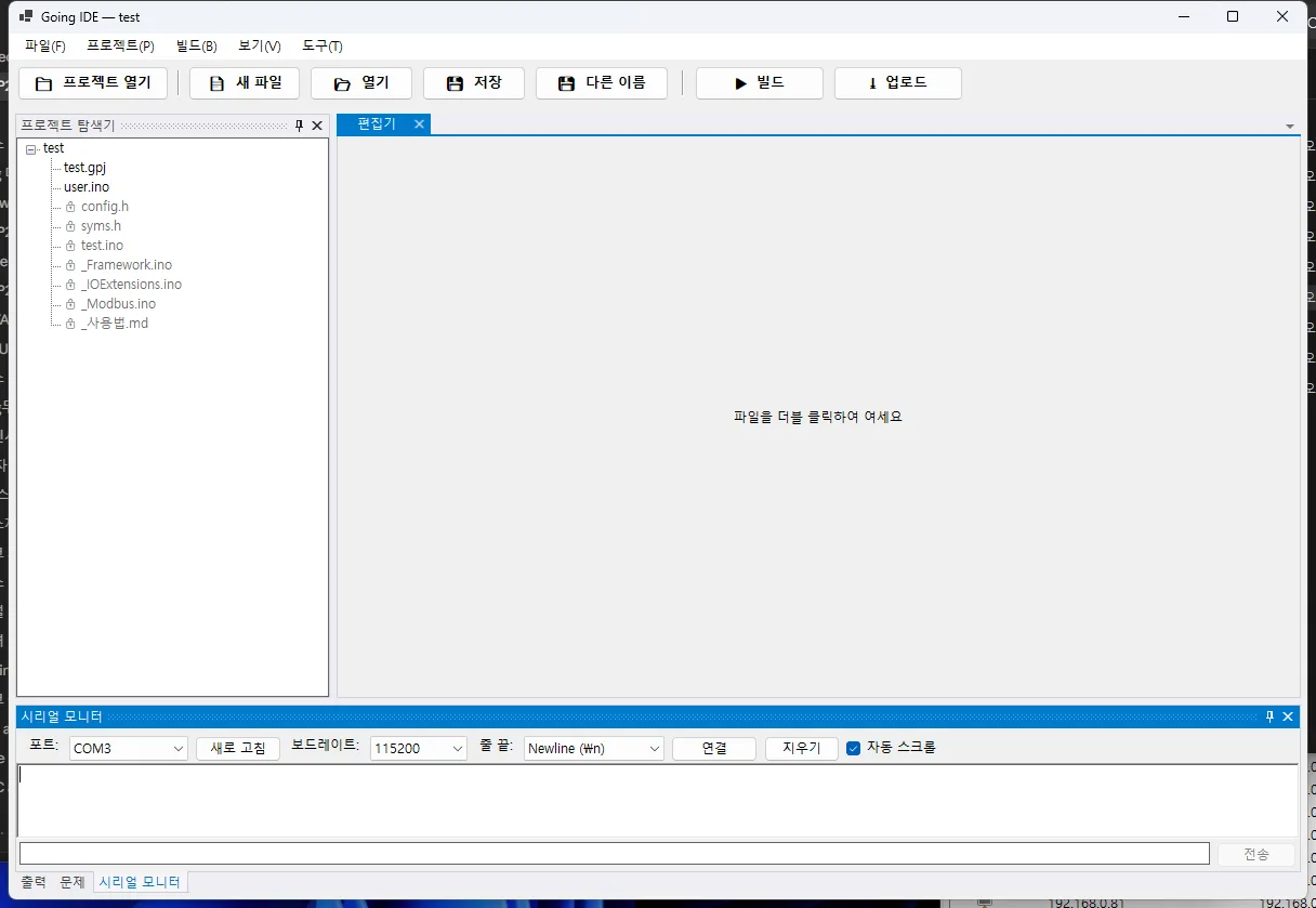 The Going.IDE main window — project explorer, code editor, serial monitor, and output/problems panels all in one window. The [Guide] button in the top right was added on 5/20.
Going.IDE is an RP2040-only IDE — a .NET 8 WinForms IDE that lets a user handle Arduino code for RP2040-based industrial PLC/HMI systems in a single window. If the Arduino IDE is “a code editor plus an arduino-cli wrapper”, Going.IDE is closer to bundling our board catalog, memory model, automatic Modbus communication generation, and HMI integration guides so that someone touching an RP2040 industrial board for the first time can have it running within an hour.
The system layout:
[user click] → [7-step wizard] → [GpjProject JSON] → [Scriban template]
                                                          ↓
[Serial Monitor] ← [arduino-cli upload] ← [arduino-cli compile] ← [user.ino + Designer.cs]
       ↓
[HMI integration guide → Claude → SenvasHMI reference doc generated]
       ↓
[automated manual PDF + Inno Setup installer]
2. The seven days of Going.IDE development
The seven-day development flow, one line per day, pulled from the commit messages.
| Date | Highlights |
|---|---|
| 5/15 (day 1) | Solution skeleton → Core (BoardCatalog/MemoryLayoutResolver/ScribanCodeGen/GpjProject) → Editor (ScintillaNET) → Build (arduino-cli wrapper) → Serial Monitor → 7-step wizard → Shell (DockPanel) — all of it in one day |
| 5/16 (day 2) | Build integration polish, EVERY_MS macro, I²C scanner dialog, dark theme, groundwork for MCP integration, 4-tier manual skeleton |
| 5/17 | (break / debugging boards on site) |
| 5/18 (day 3) | First integration on real hardware. UF2 bootstrap, RP2040 USB CDC serial debugging, I²C scan, first installer, board info exposed as MCP tools, 7 real manual screenshots |
| 5/19 (day 4) | Firmware stabilization — auto-generated English _usage.md, PCF8574 polarity regression fix, INPUT_PULLDOWN, prefer-markdown skill |
| 5/20 (day 5) | Guide dialog added — tools → guide → copy to clipboard → auto-launch Claude, plus a 4-part version scheme |
| 5/21 (day 6) | The great Modbus TCP stabilization — field-proven per-client buffers, SimpleModbusTcp standard, MCP encoding fix for Korean mojibake, manual PDF cover logo and 24 remaining screenshot placeholders filled, v1.2.0.5 installer shipped |
| 5/22 (day 7) | PICO-IO8R registered as a second main board — JSON, pin map, and 4 examples, plus a BoardCatalog regression guard |
3. The Going.IDE feature set
The IDE feature set as a cross-section by area, focused on why each choice was made.
Board catalog — JSON-driven, add a board without touching code
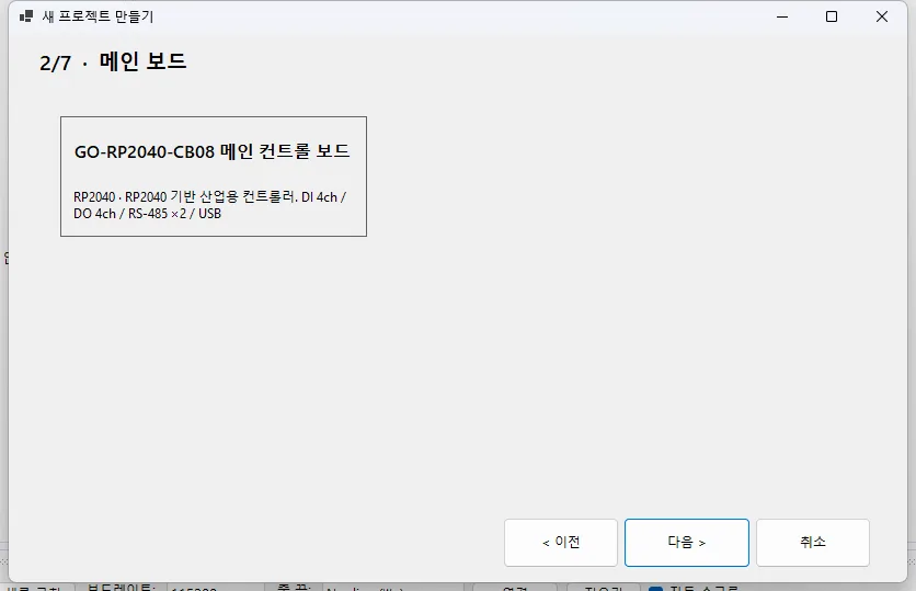 Wizard step 2 — the main board cards load automatically from JSON files. At capture time (5/18) there was only CB08; on 5/22 PICO-IO8R was added as one more card in the same form.
One file in data/boards/*.json is one board. BoardLoader reads them all by scanning the directory and puts them into BoardCatalog. Adding a board equals one JSON file, one image, and one line of test guard. The PICO-IO8R addition on 5/22 followed exactly this pattern and took 30 minutes.
{
  "id": "PICO-IO8R",
  "type": "main",
  "mcu": "RP2040",
  "fqbn": "rp2040:rp2040:rpipico",
  "pins": { "digital_input": [...], "digital_output": [...], "uart": [...] },
  "memory_model": { "P": {...}, "M": {...}, "D": {...} },
  "communications": [{ "id": "modbus_rtu_1", "type": "modbus_rtu", "uart": "Serial1" }]
}
Code generation — Scriban plus golden master tests
The GpjProject JSON produced by the wizard is passed through Framework.ino.scriban and Modbus.ino.scriban to emit a compilable .ino. Because we planted 25 golden master tests across 5 board combinations on day one, we could tell instantly what had broken no matter how many dozens of times the templates were edited over the following week.
The abstraction the firmware exposes to user functions is deliberately small:
__P[i],__M[i],__D[i]— bit and word memory areas (1 with Modbus)EVERY_MS(n) { ... },EVERY_SEC(n) { ... }— periodic execution macrosreadBit/writeBit/readWord/writeWord— memory access helpersuserSetup()/userLogic()— the two functions the user fills in
userLogic() is called every loop with no rate limit; the user states the rate explicitly with EVERY_MS. That single decision kept the firmware simple.
The 7-step wizard
Step 1 (project info) → Step 2 (main board) → Step 3 (expansion boards) → Step 4 (communication) → Step 5 (memory) → Step 6 (pins) → Step 7 (review and generate). Every step follows the same pattern: an IWizardStep interface plus an Apply(GpjProject) method. Small usability wins accumulated along the way, from a trivial fix for Korean glyph descenders being clipped in buttons (bb7e988) to automatically expanding the P area when an expansion board is added.
MCP integration — Claude driving the IDE directly
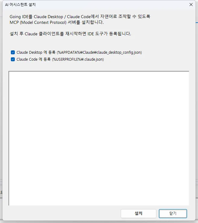 Tools → Install AI assistant. Two checkboxes and one [Install] click register the
 going-ide MCP server in both Claude Desktop’s claude_desktop_config.json and Claude Code’s .claude.json. The user only has to restart the Claude client to drive 11 IDE tools in natural language.
Going.IDE.McpServer connects to Claude Desktop and Claude Code over stdio JSON-RPC, and talks bidirectionally with the IDE’s RemoteApi over HTTP. Tools such as ide_get_project, ide_list_boards, ide_read_file, ide_write_file, ide_build, and ide_apply_example let the AI read project state, edit code, and kick off a build. This integration is the background reason an IDE could be built in a week.
The guide dialog — telling a beginner what to press first
Added on 5/20. Categories and entries from data/guides/guides.json are laid out as cards in a FlowLayoutPanel; clicking an entry copies a predefined prompt to the clipboard, auto-launches Claude, and tells the user to press Ctrl+V. We initially tried to type the prompt in automatically (d933d63), but it was unreliable, so we converged on a single pattern: clipboard plus instructions.
Manual PDF — automated capture and Markdown to HTML to PDF
docs/매뉴얼_Going.IDE.md is built with PowerShell, Pandoc, and wkhtmltopdf. The 24 screenshots were filled by a SendKeys auto-capture script (into docs/images/). The cover logo is our official corporate identity image (blue02). One build produces a finished 50-page PDF, which is packaged with the installer.
Installer — Inno Setup plus a self-contained publish
scripts/build-installer.ps1 publishes the two .NET projects, Shell and McpServer, as self-contained, gathers arduino-cli.exe, the board catalog, the examples, the manual PDF, and the Modbus TCP standard document into staging, and hands it to ISCC.exe, which emits a single Going.IDE.Setup-1.2.0.5.exe. No separate .NET 8 Runtime install is needed on the user’s PC.
4. Seven communication, serial and encoding troubleshooting highlights
IDE and firmware troubleshooting — the traps that left a mark.
(1) W5500 SPI noise — 14MHz → 4MHz → per-client buffer
Modbus TCP responses were occasionally corrupted. addr=0x70 arriving as 0x78, or qty=100 arriving as 116. Our first move was to drop the SPI clock from the Wiznet default of 14MHz to 4MHz to cut noise. It helped, but it was not the root cause.
The real cause: a single global buffer in the firmware combined with multiple simultaneous clients. With the HMI polling on one channel nothing showed, but two overlapping channels overwrote the buffer. After refactoring to the per-client struct and server.accept() pattern from our field-proven industrial board firmware (Going_Industrial), it stayed clean even back at 14MHz.
struct TcpSlot {
  EthernetClient client;
  uint8_t buf[256];
  uint16_t len;
};
TcpSlot _slots[4];

void modbusLoop() {
  EthernetClient newClient = _mbTcpServer.accept();
  if (newClient) {
    newClient.setConnectionTimeout(50);  // key to preventing a 1-second hang in stop()
    // ... assign to a free slot
  }
  for (auto& slot : _slots) { /* poll each slot independently */ }
}
(2) A socket leak in Going.Basis MasterTCP
This one was on the HMI side, in ModbusTCPMaster from the Going.Basis library. cleanup() sat inside an if (bIsOpen) guard, which meant a failed connection never called cleanup at all and sockets leaked steadily. Four leaked sockets in three hours, followed by a cascade of OperationCanceledException.
The fix: make cleanup unconditional, Shutdown(Both) then Close(), a 500ms backoff, KeepAlive 5s/1s via SIO_KEEPALIVE_VALS, and after three consecutive timeouts a forced disconnect plus a SchedulerStopException throw and drain. Shipped as Going.Basis v1.2.29-local.
(3) PCF8574 polarity — we got it wrong twice
The optocoupler (KPC18T1) on the GO-PCF8574-IN08 is an emitter follower: apply 24V, the emitter goes HIGH, the PCF8574 raw bit reads 1, which is active-HIGH. No inversion is needed, so logic: "positive" is the correct value.
We got there the hard way.
- Without looking at the circuit, we assumed “it’s an optocoupler, so it must need inverting” and set it to
negative→ every channel read 1 with no 24V applied → user report - We looked again, left it at
negative, and even wrote the regression test that way → another user report
After the second report we read the schematic (the _IN1 signal in 85-GI-I00_a GO-PCF8574-IN08.asc: U2.4 emitter to U1.4 PCF) and settled it. It is now pinned by the BoardCatalogJsonsTests.PCF8574_IN08_Logic_MustMatchActiveHighSchematic regression guard. A textbook case of not checking the circuit and trusting learned intuition tripping over the same spot twice.
(4) RP2040 USB CDC output invisible — DTR/RTS
The serial monitor was open, but the board’s Serial.println(...) output never appeared, even though the arduino-cli console showed it. We burned a lot of time on this. It came down to one line: SerialPort.DtrEnable = true; RtsEnable = true;. RP2040 USB CDC watches the host’s DTR line to decide whether a terminal is attached, and the default in our .NET WinForms code was false.
(5) Serial monitor auto-reconnect — _suspendAutoReconnect
Right after a firmware upload, USB re-enumerates and the port briefly disappears. If the monitor tried to reconnect and failed, the user had to reconnect by hand. The fix: set _suspendAutoReconnect = true when an upload starts, and have ResumeAfterUpload() wait and then attempt an automatic reconnect when it finishes.
The trap: an early-return branch failed to reset _suspendAutoReconnect = false, so it stopped working from the second upload onward. One line, and it was stable.
(6) Build lock — the dll is held while Going.IDE.Shell is running
dotnet test tries to copy bin\Debug\...\Going.IDE.Core.dll while Shell.exe is holding it, and you get MSB3027. The fix is obvious (“close Shell”), but the real lesson is the structure underneath: the Tests project’s csproj pulls Shell’s .dll into its own bin as well. Splitting the output directory or trimming the ProjectReference set would be cleaner (not fixed yet).
(7) Korean mojibake — Console encoding in McpServer
Copy a prompt from the guide dialog, paste it into Claude Desktop, and the Korean text arriving at the MCP server came out mangled: 연결 became ?곌껐.
The cause: the default .NET Console encoding on Korean Windows is CP949. The stdin JSON-RPC Claude sends is a UTF-8 byte sequence, and the CP949 decoder treats the lead byte as invalid and substitutes ?. All the Korean inside the JSON comes out broken.
The fix is two lines in Program.cs.
Console.InputEncoding = System.Text.Encoding.UTF8;
Console.OutputEncoding = System.Text.Encoding.UTF8;
Every stdio MCP server is exposed to this same trap. It is a barrier to entry on Korean, Japanese, and Chinese Windows that two lines remove.
5. AI coding patterns — what made a week possible
AI coding patterns are the decisive reason Going.IDE came together in a week — the patterns that come naturally once you work with AI. Three of them:
Golden master tests, so templates can be edited freely
On day one, 5/15, we planted 25 golden master tests across 5 board combinations for the Scriban templates (CB08 only / CB08+IN08 / CB08+RY08 / CB08+IN08+RY08 / CB08+W5500). No matter how many times the AI reworks a template, one diff shows what changed. The templates changed explosively over the week, with zero regressions.
Automated manual capture
The scripts/capture-*.ps1 PowerShell scripts launch the IDE, open menus with SendKeys, and capture PNGs. All 24 placeholders were filled automatically. When a 50-page manual PDF completes in one build, the nagging weight of “the manual is out of date” shrinks while you build the next feature.
MCP plus a skill system — the AI recognizes its own territory
Put keywords in the frontmatter of a document like data/mcp-skill/modbus-tcp-patterns.md (W5500, MasterTCP, EthernetServer, FC03/FC06, and so on) and Claude loads it automatically when working on Modbus TCP. Before the user even asks “how do we make Modbus reliable?”, the AI already knows the standard pattern. The AI fetches the standards for a work area without a single menu click.
6. RP2040-only IDE recap — one week of output
| Item | Result |
|---|---|
| Solution projects | 12 (Core / Modules.* × 8 / Shell / Tests / McpServer) |
| Unit tests | 447 passing |
| Board catalog | 5 (CB08 / IN08 / RY08 / W5500-LINK / PICO-IO8R) |
| Example catalog | 7 (split per board) |
| Manual | 50-page PDF, 24 screenshots |
| Installer | Going.IDE.Setup-1.2.0.5.exe (self-contained, no separate .NET 8 install) |
| MCP tools | 11 (project / boards / files / build / examples) |
Next up are more boards in the lineup (PICO-IO8R is the one addition so far, differentiated by RS-232 and FRAM) and HMI tool integration (bidirectional .gudx with SenvasHMI). And the most important item: getting one real user on site to actually pick this up and build a PLC with it.
An IDE, once it exists, grows itself. Adding one entry to the guide dialog now costs about as little as adding one section to a manual chapter. One week to reach this point — the biggest finding is that AI coding has redrawn the cost curve for an entire category called “the IDE”.
A dedicated IDE ran on a cycle of nailing the skeleton down in one day and spending the remaining six fixing traps found on real boards — AI coding changed the ROI of building one.
Contact
- Email: [email protected]
- Instagram: https://www.instagram.com/going.sen/
- Website: https://intosen.com/kr/consult/
Comments
Enter a nickname to leave a comment, or sign in with Google or GitHub.