
We built an RP2350 touch LCD timer to control the ride time of a horse-riding machine.
The ride time is set on screen, and the MM:SS countdown starts from the moment the inverter is confirmed to be actually running.
When the set time runs out, the controller sends a STOP command automatically and then confirms that the machine has actually stopped.
- Riding-machine mode setting
- Countdown
- Automatic stop
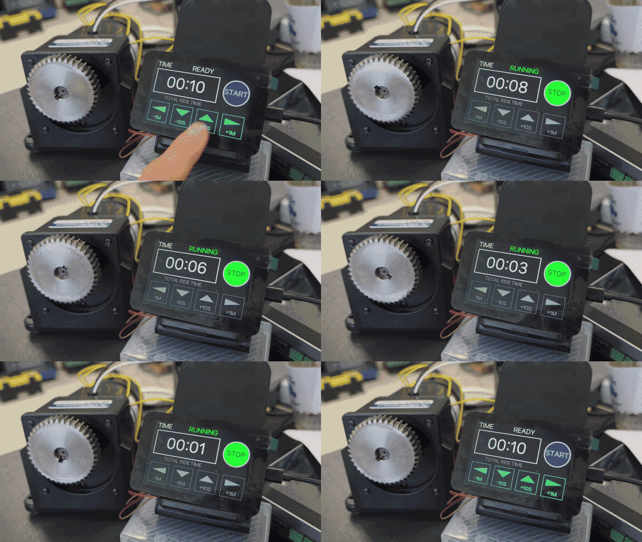
Setting the ride time on the RP2350 touch LCD and watching the countdown run
What the RP2350 touch LCD timer does
The ride time control screen has the following functions.
| Function | Applied |
|---|---|
| Ride time setting | 10 seconds to 30 minutes, adjusted with -1 min, -10 s, +10 s, +1 min |
| Time display | Remaining ride time shown as MM:SS |
| Countdown start | Starts after inverter RUN feedback and actual frequency are confirmed, not on the START touch |
| Setting lock | Time changes are blocked while running, while confirming start, and while confirming stop |
| Automatic stop | When time expires, sends STOP and then confirms the actual stopped state |
It sounds complicated, but in the end the TFT LCD time setting was split into 10-second and 1-minute steps to match real use.
The -10S and +10S buttons make small adjustments, and -1M and +1M change long durations quickly.
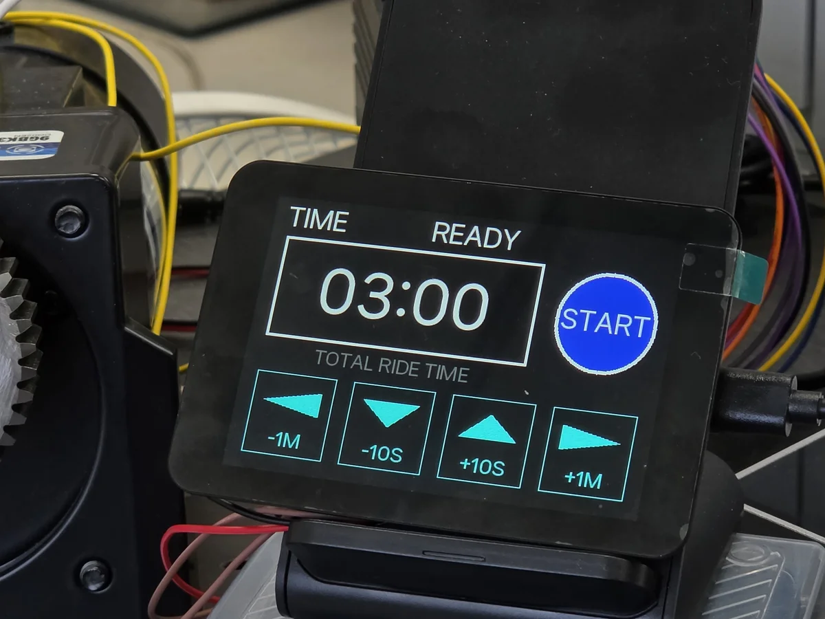
RP2350 touch LCD timer screen in READY state with the ride time set to 03:00
The feedback after pressing START
An RP2350 countdown timer for equipment control has to distinguish between the moment START is pressed and the moment the motor actually starts moving.
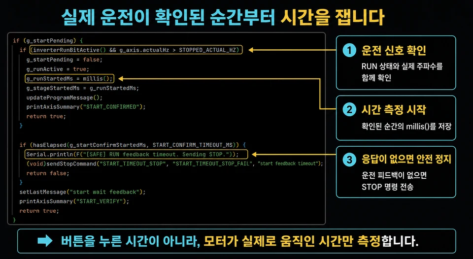
Code that stores the millis value at the moment inverter RUN status and actual frequency are confirmed as the ride start time
Don’t do it this way.
START touched
→ countdown starts immediately
→ check whether the inverter is running
Between the button input and the actual motion there is RS485 communication and the inverter’s response. If the countdown starts from the START touch, time during which the motor is not yet moving gets counted as ride time.
Do it this way.
START touched
→ send the run command
→ confirm RUN status and actual frequency
→ store the confirmed time as the ride start time
→ start the countdown
If the run feedback is not confirmed within the allowed time, the countdown does not start and a STOP command is sent instead. This is why the controller checks the actual equipment state rather than trusting the START input on screen.
Elapsed time from millis instead of delay
A delay-based approach blocks screen updates, touch input, and RS485 communication while it waits.
So the timer does this instead.
elapsed   = current millis - actual ride start millis
remaining = set ride time - elapsed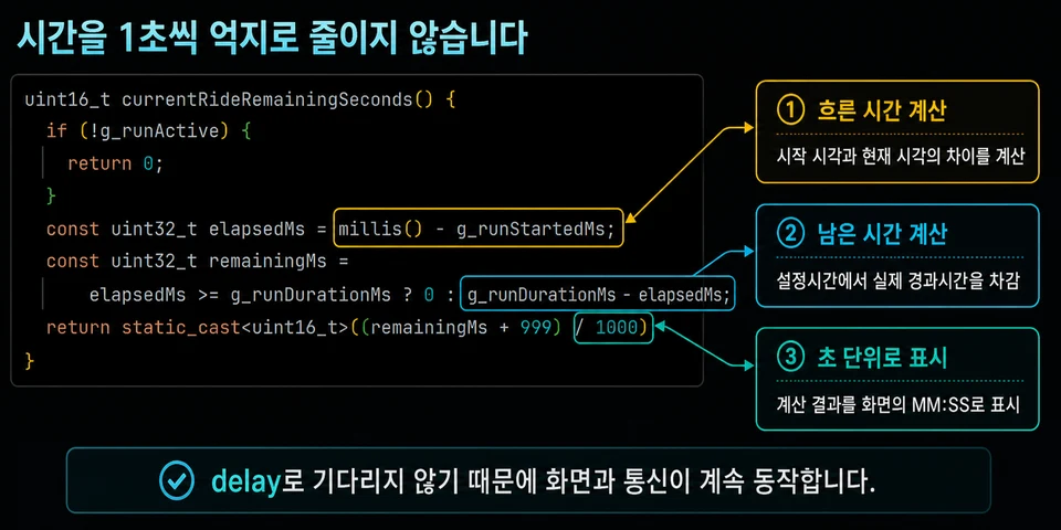
Code that computes elapsed and remaining time from the millis difference and converts it to seconds
Because it calculates the real elapsed time instead of waiting, the screen and the communication loop keep running during the countdown. The result is converted to seconds and shown in the LCD’s MM:SS area.
The set time cannot be changed while running
If the time setting could be changed while the machine is moving, the end time of the current ride would shift. In a ride that switches speed in several stages, the per-stage reference times would shift as well.
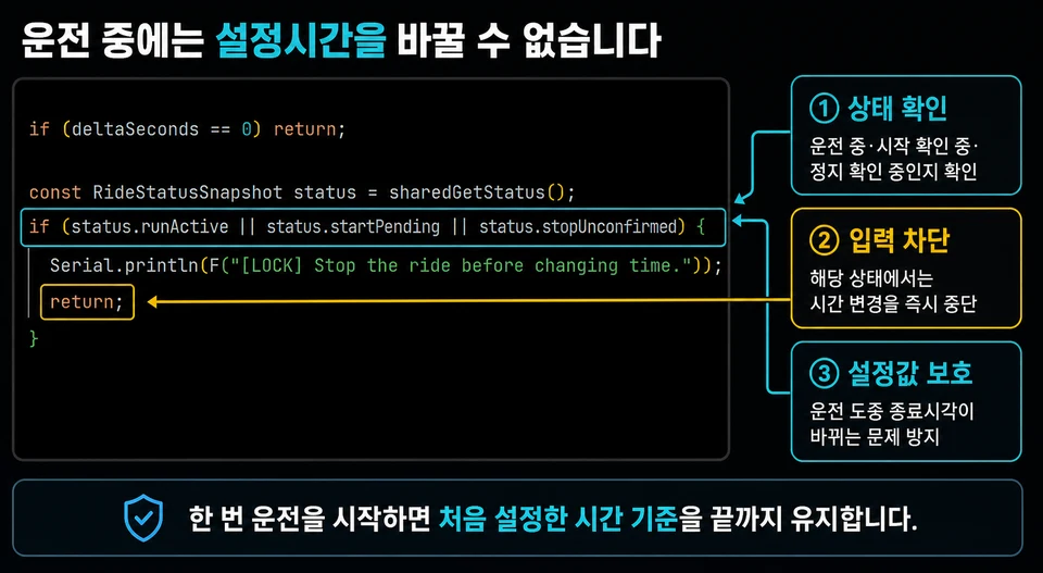
Code that blocks time-change input while running, while confirming start, and while confirming stop
Once a ride starts, the total ride time fixed at the start is kept until the end. The next ride time is changed after the machine returns to the READY state. Time adjustment input is therefore blocked in these states.
- RUNNING, after the inverter run is confirmed
- Waiting for run feedback after the START command
- Confirming the actual stop after the STOP command
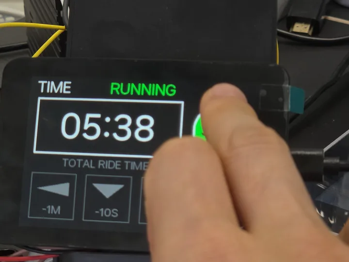
RP2350 touch LCD timer in RUNNING state with the countdown at 05:38
Problems found in the RP2350 timer and how they were handled
| Don’t do this | What can go wrong | Do this instead |
|---|---|---|
| Start the countdown on the START touch | Time before the motor moves is counted | Start after RUN feedback and actual frequency are confirmed |
Decrement once a second with delay(1000) | Screen and communication lag, the clock drifts | Compute real elapsed time from the millis() difference |
| Allow time changes while running | End time and stage transitions shift | Lock the setting while running, confirming start, confirming stop |
Treat 00:00 as an actual stop | A machine still decelerating is shown as stopped | Confirm the stop with RUN cleared and the actual frequency |
| Keep running with no communication response | The timer advances without knowing the inverter state | Send STOP when feedback times out |
Can a ride timer work without an RTC?
An industrial equipment timer UI that measures ride time and remaining time does not necessarily need an RTC. millis() is enough to calculate how much time has passed since power-on.
An RTC or another time reference should be considered when the current date and time must be displayed, or when time must be tracked while the power is off. This feature is not a clock that shows the current time; it is a countdown timer that controls one ride on the riding machine.
RP2350 touch LCD timer summary
What matters in an RP2350 touch LCD timer is not just decrementing a number on screen once a second.
- Set the total ride time on the touch LCD.
- Start counting from the moment inverter RUN feedback and actual frequency are confirmed.
- Compute remaining time from
millis()elapsed time. - Lock the time setting while running.
- After the time expires, separate the STOP command from the actual-stop confirmation.
In an equipment-control timer, button input, actual run feedback, the countdown, and automatic-stop confirmation have to be linked into a single flow.
Contact
- Email: [email protected]
- Instagram: https://www.instagram.com/going.sen/
- Website: https://intosen.com/kr/consult/
Comments
Enter a nickname to leave a comment, or sign in with Google or GitHub.