
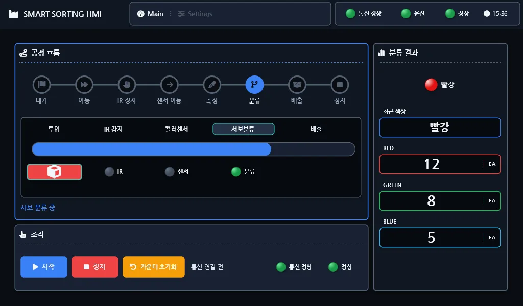
We pulled the Bluetooth link and the smartphone app off an Arduino sorting-line teaching kit and reconnected
it to an industrial touch HMI (Senvas Touch) over wired Modbus RTU. The board moved from an UNO to a
Mega 2560, and the original serial delay() sequence was rebuilt from scratch as an eight-stage state machine
driven by millis(). The communication contract was pinned down as a Holding Register table (40001–40101)
before any code was written. The result is a single HMI screen with start, stop and reset, an animated view of
the process stage, and live cumulative R/G/B sorting counts.
The original Bluetooth kit and where it stops
This Arduino sorting-line teaching kit ships as a classic sketch: everything in one file, 15_conveyer_belt_bluetooth.ino. Conveyor
belt, IR sensor, TCS34725 color sensor, servo sorter, NeoPixel LEDs and an HC-05 Bluetooth module all live
together, exchanging single-character commands (s, 0, 1, r/g/b) with a smartphone app built in App
Inventor (smart_factory_advancedUI.aia).
For a demo that is plenty. You can see what is happening, and driving it from a phone feels natural. The limits only start to show once you want it to behave like a real HMI bolted to the side of a line.
- You have to be holding a phone. There is no panel-mounted HMI.
- There is no cumulative sort count and no process-stage progress. Nothing tells you which stage you are on or how many red, green and blue parts have piled up.
- There is no distinction between a lost link and a device fault. When Bluetooth drops, the app simply stops responding.
- Pairing is one-to-one, so two people cannot watch the same screen.
Those four things together are what “does not feel like an industrial HMI” actually means.
Moving to Senvas Touch and Modbus RTU
Senvas Touch is an industrial touch HMI that acts as the Modbus RTU master. It reads and writes registers on a cycle (we are not going into its internals here — “it reads and writes exactly what the table says” is the whole story).
Choosing Modbus RTU was easy. It is the common language of the plant floor, and being wired puts its reliability and determinism above anything wireless. Slave IDs and register addresses give you many-to-many expansion later (this build is one-to-one). Bluetooth brings pairing management, reconnect delays and dead spots; going wired makes all of that disappear at once.
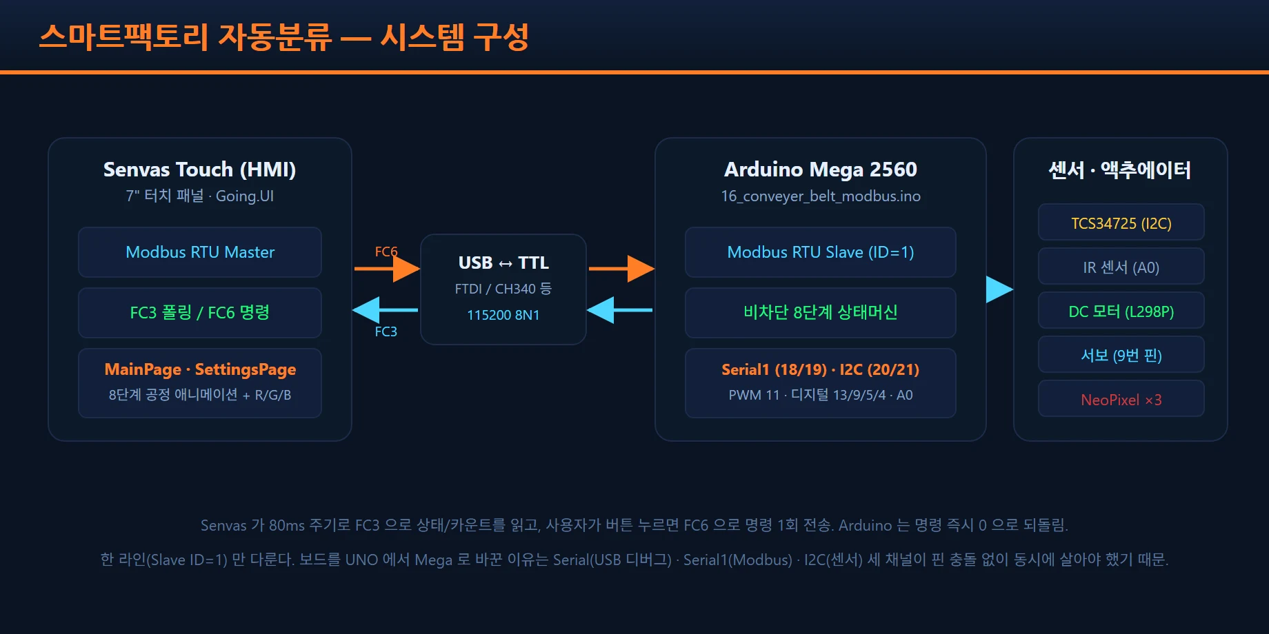
After the change the chain looks like the block diagram above: Senvas Touch → USB-to-TTL converter → Mega
Serial1 (RX1 = pin 19, TX1 = pin 18) → sensors and actuators. The USB-to-TTL converter takes the RS-485
signal from the HMI down to UART levels for the Mega.
Design document first: the Holding Register contract
The Holding Register map was finalized in two documents, design.md and arduino-modbus-rtu-protocol.md,
before any code was opened. Communication is, in the end, a contract that says “this value lives at this
address”. Both sides read the same table and implement independently.
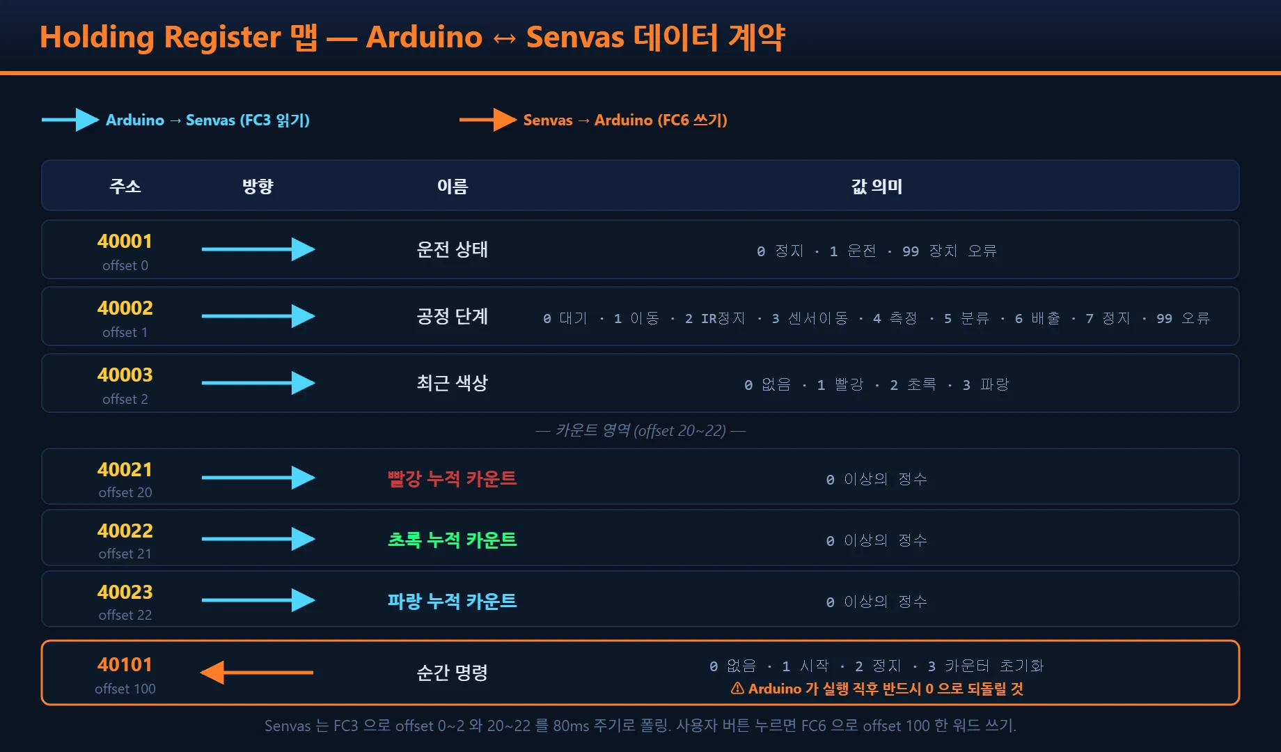
| Address | 0-base | Direction | Meaning | Values |
|---|---|---|---|---|
| 40001 | 0 | Arduino → HMI | Run state | 0 = stopped, 1 = running, 99 = device fault |
| 40002 | 1 | Arduino → HMI | Process stage | 0 = idle … 7 = stopped, 99 = fault |
| 40003 | 2 | Arduino → HMI | Last color | 0 = none, 1 = red, 2 = green, 3 = blue |
| 40021~40023 | 20~22 | Arduino → HMI | Cumulative R/G/B counts | integer |
| 40101 | 100 | HMI → Arduino | Momentary command | 0 = none, 1 = start, 2 = stop, 3 = reset |
The firmware pins these addresses down as constants, so a later change to the table propagates from a single number.
const uint16_t REG_RUN_STATE   = 0;    // 40001  run state
const uint16_t REG_STAGE       = 1;    // 40002  process stage
const uint16_t REG_COLOR       = 2;    // 40003  last color
const uint16_t REG_RED_COUNT   = 20;   // 40021
const uint16_t REG_GREEN_COUNT = 21;   // 40022
const uint16_t REG_BLUE_COUNT  = 22;   // 40023
const uint16_t REG_COMMAND     = 100;  // 40101  momentary command, HMI to Arduino
The command register at 40101 has one rule: the Arduino must write it back to zero the instant it acts on the command. The HMI does not write that register on a cycle — it only puts a value there when a button is pressed. If the Arduino never clears it, the same command can be executed again on the next polling cycle. The “execute exactly once” guarantee rides on that one line.
void handleCommand() {
  uint16_t cmd = holdingRegisters[REG_COMMAND];
  if (cmd == CMD_NONE) return;

  switch (cmd) {
    case CMD_START: if (runState != RUN_ERROR) startRunning(); break;
    case CMD_STOP:  if (runState != RUN_ERROR) stopRunning();  break;
    case CMD_RESET: redCount = greenCount = blueCount = 0;     break;
  }
  // A momentary command must be cleared to 0 immediately (guarantees single execution)
  holdingRegisters[REG_COMMAND] = CMD_NONE;
}
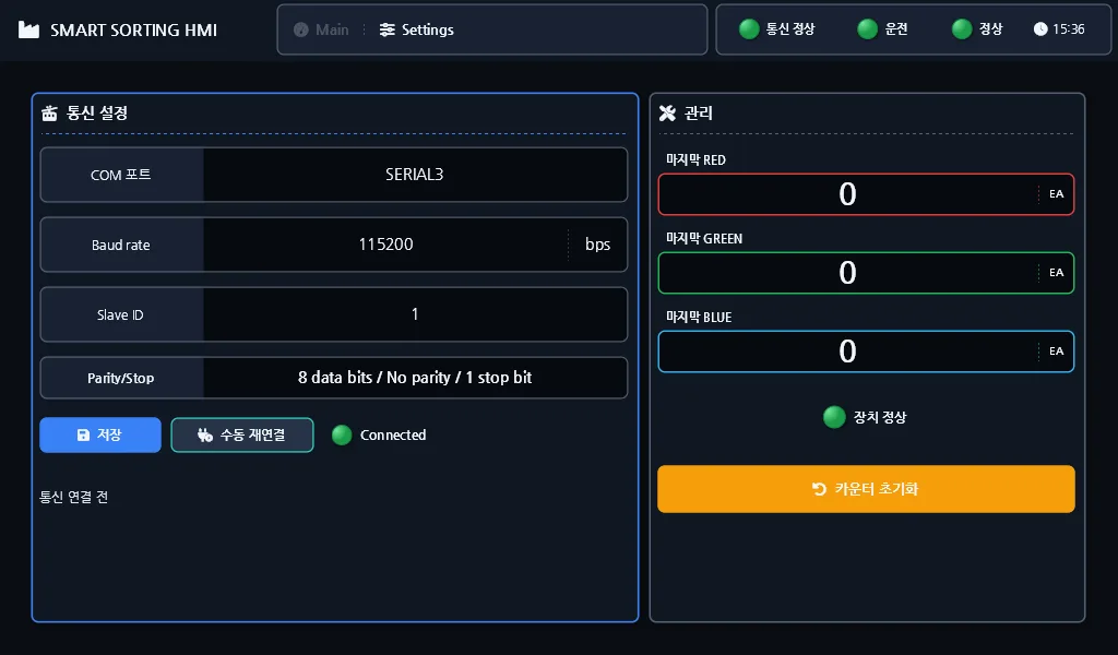
When communication drops, the HMI disables every command button. The screen below is that state: the last counts received are still carried over on the display, but operation itself is locked out.
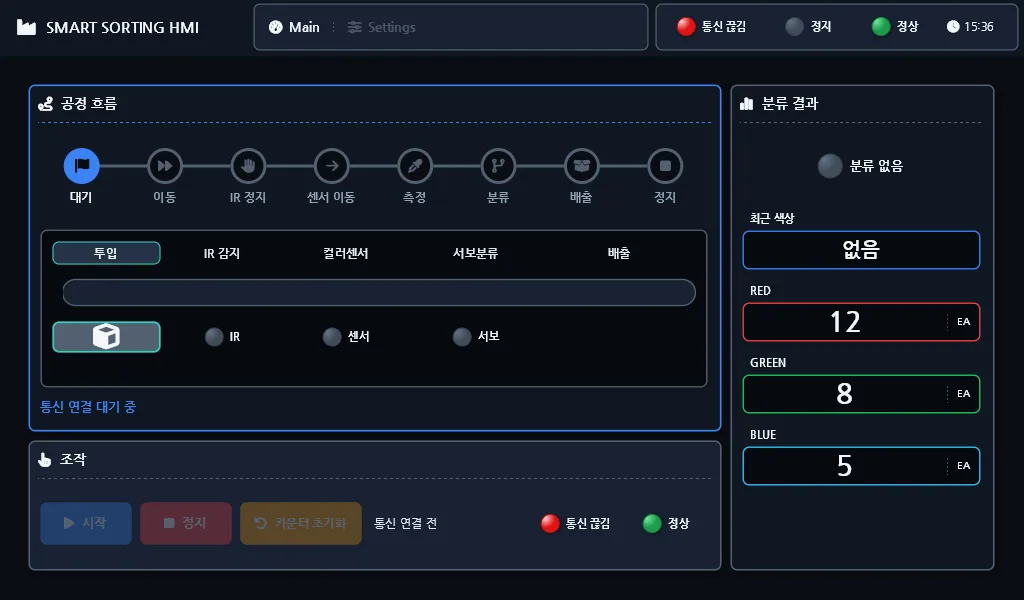
The link itself is configured on a separate screen — COM port, baud rate, slave ID, parity and stop bits, then save.
Hardware decision: UNO to Mega 2560
Our first thought for the Arduino Modbus RTU slave was to keep the UNO and run Modbus over SoftwareSerial. It does not work. Three things were needed at the same time.
- Modbus RTU serial — 115200 baud, which needs a solid hardware UART. SoftwareSerial has a high error rate at that speed and collides with other interrupts.
- USB serial — for debug output. Sharing a port with Modbus mixes the two streams.
- I2C — for the TCS34725 color sensor.
The UNO has exactly one hardware UART, so Modbus and USB debug cannot both be alive. The Mega 2560 gives
you Serial (USB), Serial1 (pins 18/19), Serial2 (pins 16/17) and Serial3 (pins 14/15) as separate
ports, with I2C on its own digital pins 20 and 21.
The pin assignment ended up as:
- Modbus (Serial1): TX = pin 18, RX = pin 19
- I2C (TCS34725): SDA = pin 20, SCL = pin 21
- DC direction = 13, DC speed (PWM) = 11, servo = 9, NeoPixel = 5, buzzer = 4, IR = A0
Once we moved to the Mega, pin conflicts stopped being a concern.
Firmware core: rip out every delay() and build a state machine
Before the state machine replaced delay(), the original flow was delay(2000) → delay(1500) → delay(1500) → delay(1000). Each step — the conveyor
moving, the IR sensor detecting, the color sensor reading, the servo sorting — was a blocking wait.
That is easy to read in a teaching sketch. In a Modbus slave it is fatal. While delay(2000) runs, loop() is
frozen and so is Modbus polling. After a few failed reads in a row, the HMI decides the link is down. You end
up with a machine that works while the HMI insists it cannot connect.
The fix is to remove every delay() and switch to a millis()-based state machine. One pass of loop()
has to finish within a few milliseconds. Anything that needs time records “when this stage was entered” and
compares elapsed time on the next pass to decide whether to move on.
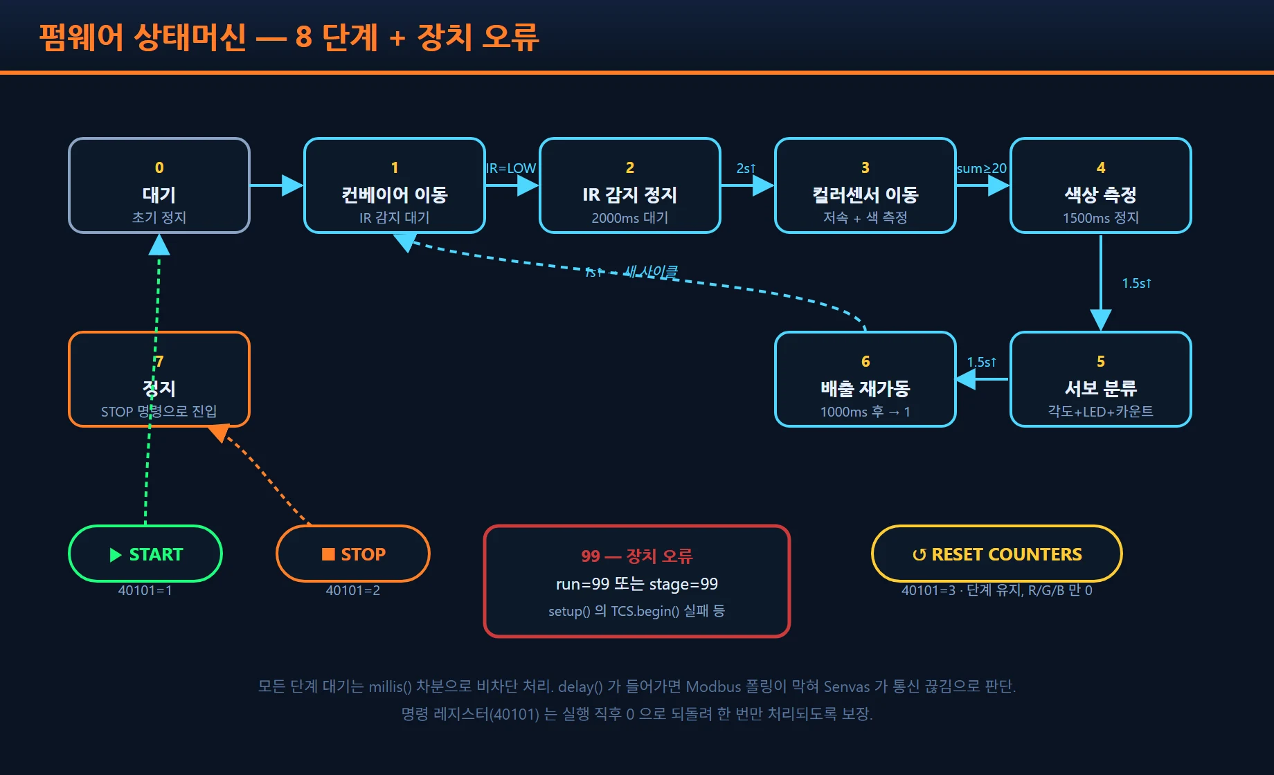
We split the process into eight stages.
START command (40101=1)
   │
   ▼
[0 Idle] ──start──▶ [1 Belt moving] ──IR detect──▶ [2 IR stop (2s)]
                                                          │
                                                          ▼
                        [3 Move to color sensor (slow)] ◀──┘
                                  │ sum ≥ 20
                                  ▼
                        [4 Measure color (1.5s)]
                                  │
                                  ▼
                        [5 Servo sorting (1.5s)]
                                  │
                                  ▼
                        [6 Resume discharge (1s)] ──▶ back to [1]

STOP command (40101=2)  → [7 Stopped]
RESET command (40101=3) → counters cleared to 0 (stage unchanged)
One stage of the machine looks like this. It reads the sensor, and when the value crosses the threshold it transitions. This block runs in microseconds.
case STAGE_TO_COLOR: {
  uint16_t rawR, rawG, rawB, rawC;
  tcs.getRawData(&rawR, &rawG, &rawB, &rawC);
  int r = map(rawR, 0, 21504, 0, 1000);
  int g = map(rawG, 0, 21504, 0, 1000);
  int b = map(rawB, 0, 21504, 0, 1000);
  if (r + g + b >= COLOR_SUM_THRESHOLD) {
    railStop();
    if      (r > g && r > b) lastColor = COLOR_RED;
    else if (g > r && g > b) lastColor = COLOR_GREEN;
    else                     lastColor = COLOR_BLUE;
    enterStage(STAGE_COLOR_MEASURE);
  }
  break;
}
With the state machine in place, Modbus polling and the process logic no longer compete inside loop(), and
polling never falls behind.
Three Modbus RTU debugging stories
Modbus RTU debugging is where most of the time went. Writing it down is probably the most valuable part of the whole job.
One: the library is installed but the IDE cannot find it
The symptom was clean: Adafruit_TCS34725.h: No such file or directory. The library was definitely installed
through the library manager, and the build still failed.
The cause was a path mismatch. arduino-cli had installed the library into its default location (where the OS had placed the sketchbook path, inside an auto-syncing folder), while the Arduino IDE’s sketchbook pointed at a separate folder on another drive. The IDE only ever looks inside its own sketchbook.
Running arduino-cli config dump (or checking directories.user in ~/.arduinoIDE/arduino-cli.yaml) shows
the real install path. When the two paths differ, a library ends up “installed but invisible”. The fix is
either to repoint the IDE’s sketchbook or to copy the library into that folder directly.
Two: total silence on the line — the v3.x library trap
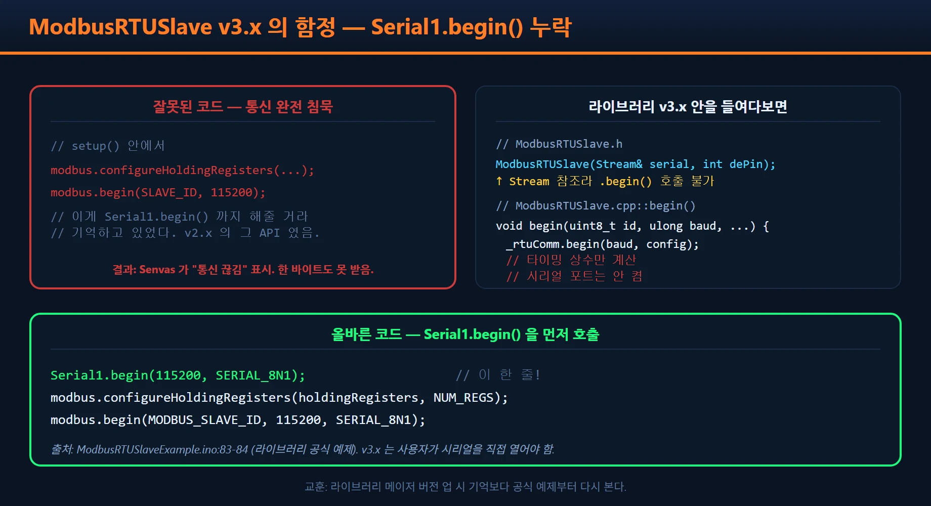
This one took the longest. It built. It uploaded. Senvas showed nothing but “communication lost”. We checked the wiring three times. Baud rate matched. Slave ID was set to 1. Still silence.
In the end we opened the library source. CMB27’s ModbusRTUSlave v3.x does not start the serial port inside
modbus.begin(). The constructor only takes a Stream& reference, so there is no polymorphic way for it to
call serial.begin(). The user has to call Serial1.begin() first.
The library’s own example (ModbusRTUSlaveExample.ino) makes this explicit on lines 83 and 84, split into two
separate calls.
// The v3.x trap: leave this one line out and the line goes completely silent.
Serial1.begin(MODBUS_BAUD, SERIAL_8N1);
modbus.configureHoldingRegisters(holdingRegisters, NUM_HOLDING_REGISTERS);
modbus.begin(MODBUS_SLAVE_ID, MODBUS_BAUD, SERIAL_8N1);
The API shifted slightly between v2 and v3. Code written from memory does not catch a change like that. When a library goes up a major version, the official example is the first thing to reread.
Three: communication works but nothing moves — install diagnostics
With the second problem fixed, a different symptom appeared. Senvas was reading the run state and the counts, but pressing START did not turn the motor.
Instead of guessing, we put diagnostic logging on USB serial. On the Mega, Serial (USB) and Serial1
(Modbus) are fully separate, so log output cannot disturb Modbus traffic.
#define DEBUG_USB_SERIAL 1     // set to 0 and it all disappears at compile time

void serviceHeartbeat() {
  DBG(F("[HB] run=")); DBG(runState);
  DBG(F(" stage="));   DBG(stage);
  DBG(F(" cmd="));     DBG(holdingRegisters[REG_COMMAND]);
  DBG(F(" R/G/B="));   DBG(redCount);
  DBG(F("/"));         DBG(greenCount);
  DBG(F("/"));         DBG(blueCount);
  DBG(F(" IR="));      DBGLN(digitalRead(PIN_IR));
}
This is what came out in the Serial Monitor.
[BOOT] 16_conveyer_belt_modbus 시작
[BOOT] TCS34725 OK (I2C SDA=20 SCL=21)
[BOOT] Modbus RTU Slave id=1 baud=115200 8N1 on Serial1 (Mega: 핀19=RX1, 핀18=TX1)
[HB] run=0 stage=0 color=0 cmd=0 R/G/B=0/0/0 IR=1
[CMD] received=1  runState=0
[STAGE] 0 -> 1
[CMD] received=1 was printing, so the command was arriving. But no [STAGE] transition followed. The problem
was not the command handling at all — it was the color sensor initialization inside startRunning(), where
I2C was not answering.
That led to one more finding. I2C pins differ per board. The UNO uses A4/A5, the Leonardo uses 2/3, and the Mega uses 20/21. We had swapped the board for a Mega but left the wiring on A4/A5. Moving it to 20/21 brought the color sensor back.
There is a saying that 80% of debugging is working out where things stopped. One heartbeat log line saved half an hour of guessing.
Recap of the Modbus RTU sorting line and what is next
On this Modbus RTU sorting line, start, stop and reset, all eight process stages, and the cumulative R/G/B display now work correctly. Motor PWM is set slow at 50/40 to suit a demo (watch out for the PWM dead zone — below it the motor simply will not turn).
If we had to compress what this job taught us into one line: attaching a teaching kit to an industrial HMI was not just a change of communication method. The way time is handled (delay to state machine) and the debugging tools (USB logging plus reading library source) had to change with it.
Things we would like to try next:
- Persist the counts to EEPROM — keep cumulative R/G/B values across a power cycle
- Calibrate the color thresholds from the HMI — values are hardcoded today; they should be adjustable from the settings screen
- Several lines on one HMI — separate slave IDs so line 2 and line 3 can be monitored from the same panel
- A separate alarm history screen — a record of how often device faults occurred
Of the three debugging stories, the v3.x library trap was the most deflating. The code looked completely fine and the line was completely silent; there was no way to find the cause without opening the library source. Next time a symptom looks like that, we will probably open the library’s example before checking the wiring again.
The core of a Modbus RTU sorting line is fixing the register contract before writing code, and replacing delay() with a state machine so polling never stalls.
Kit used — this project was built with the eduino smart factory kit.
Contact
- Email: [email protected]
- Instagram: https://www.instagram.com/going.sen/
- Website: https://intosen.com/kr/consult/
Comments
Enter a nickname to leave a comment, or sign in with Google or GitHub.