
We built an industrial HMI that connects several drive control boards over Modbus TCP so that every powered device on a stage can be monitored and operated from a single touch panel. This post covers the design intent, the implementation, and the awkward problems we ran into on site. It is a real project built on SENVAS HMI.
This system has an earlier version: a Raspberry Pi based stage lighting control HMI, which we covered in its own post. That first version was built around lighting; this second version widened the scope to stage machinery in general (Machine and RD devices).
1. What the stage control HMI project is
Small theater stage automation starts with dozens of devices on one stage — masking borders, lifts, suspensions, screens, spotlights, curtains, banners. They generally fall into two groups: directional drives (Machine) and simple ON/OFF loads (RD). TheaterControl is the HMI that puts all of them on one 1024×600 touch panel.
The center of gravity in the design was not a rich information display. It was a single question:
“Is it safe to press this device right now, or not?”
In stage control the real danger is rarely a shortage of information. It is hitting the wrong channel, or mistaking a device with a dead link for a healthy one. So the screen lays every device out on an equal grid of cards, leaves healthy cards quiet, and lets only the abnormal states — running, limit reached, alarm, communication lost — jump out through color and disabled controls.
| Item | Detail |
|---|---|
| Purpose | Real-time monitoring and control of stage drive and ON/OFF devices |
| Screen | 1024×600 touch panel, modern-style, DarkSkyblue theme |
| Communication | Modbus TCP client, several boards connected at once |
| Deployment | linux-arm64 touch panel (SENVAS touch launcher) |
| Scope | Real-time control, board/channel configuration, communication and safety status (no history logging) |
2. Touch panel screen layout
The industrial touch panel HMI has three pages: Machine control, RD control, and settings. A shared header carries the screen name (the touch panel shows it as Stage Control), the current page, and on the right a compact cluster of board communication (COMM), EMG, FAULT, and a software emergency stop (S-EMG) with its status and button. Faults on an individual device show up on the card border or button color; faults at board level are read from this shared status area.
2.1 Machine control
The operating screen for devices with a driven direction, eight per page. The active channels of every board are concatenated in board order and then channel number, and the left/right arrows page through them eight at a time.
Each card carries device name, icon, ON/OFF, UP (OPEN), STOP, and DOWN (CLOSE).
- The direction currently running is green (Good); once that direction hits its limit it turns orange (Warning).
- A channel alarm such as EOCR (overload) turns the card border red (Danger) and blocks operation of that card alone.
- Curtain channels label their buttons
OPEN/CLOSE; everything else usesUP/DOWN.
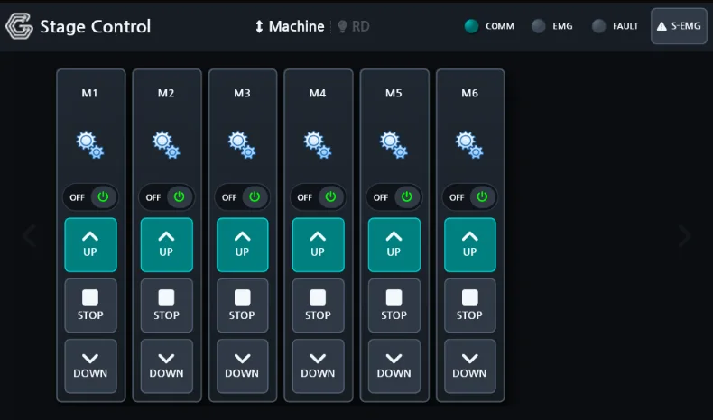
The Machine control screen. Every card has ON/OFF, UP, STOP, and DOWN. The running direction shows green, a reached limit shows orange, and a channel alarm turns the card border red immediately.
2.2 RD control
The screen for simple ON/OFF devices, packed 8 columns by 3 rows into 24 slots. A card holds only the device name, an icon, and an ON/OFF switch. Only RD channels that were detected and have an icon assigned are shown, and anything past 24 slots moves to the next page.
The RD screen has one special gesture — drag-band group control. Dragging a rectangle across the cards selects everything it overlaps, and releasing brings up a “N channels — ON / OFF / Cancel” confirmation popup so they can be switched together. A single tap still toggles just that one channel. (Implementation in §5.4.)
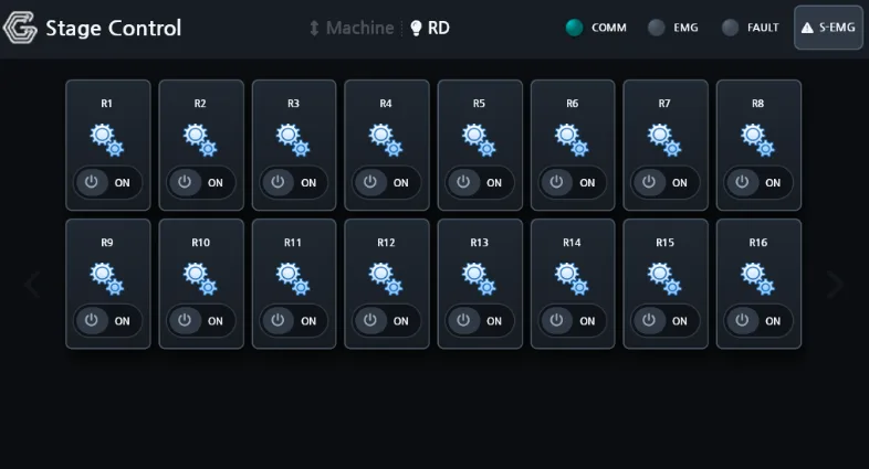
The RD control screen. An equal grid of ON/OFF cards (16 channels in this configuration). Dragging a rectangle over the cards selects everything underneath so it can be switched on or off in one action.
2.3 Settings
This is where the actual board and channel configuration is built. Tabs split it into board settings, Machine channels, and RD channels.
- Board settings: add and remove boards, edit name, IP, Port, Unit ID and enabled flag, test the connection, auto-discover boards by scanning the subnet, and detect devices.
- Machine/RD channels: assign a name and icon to each detected channel. A channel with no icon is treated as unused and never appears on the operating screens. In other words, we do not dump every physical channel the scan finds onto the operating screen — only the devices the site operator has explicitly claimed.
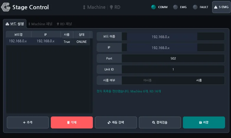
The board settings tab. Communication parameters (IP, Port, Unit ID) for each registered board are edited
here, and auto-discovery plus device detection fill in the channels. In this shot the board is ONLINE with
6 Machine and 16 RD channels detected. (The board IP is masked.)
3. System architecture
The HMI system architecture splits communication, persistence, and the periodic logic into three layers.
[Configuration]   Load and serve saved board/channel settings (board list, channel names/icons)
     │
[Communication]   Modbus TCP connection per enabled board
     │            · Poll status registers
     │            · Refresh detection results
     │            · Write event commands
     │
[Periodic logic]  Drive the 50ms status refresh
     │            · Summarize connection / FAULT / EMG / comm faults per board
     │            · Compute which channels the operating screens may show
     │
[Screens]         Machine/RD cards render the displayable channels in board order
                  Settings page edits the configuration and validates on save
The core design rule is “pages know nothing about registers.” Every line that decodes a Modbus register
into bits lives in the board and channel data model, and pages only read finished state (On, CanCommand,
HasAlarm, and so on) to draw with. That means a change to the communication contract never touches the
screen code.
We kept the skeleton code generated by the SENVAS designer untouched and wrote all communication, persistence, and periodic logic in the user code area only. Keeping the generated skeleton and the hand-written logic apart means rebuilding the design never wipes out hand-written code.
4. Modbus TCP communication and data model
As a Modbus TCP multi-board client, the HMI connects to each registered board. The board is the unit of
communication and the channel is the unit of display and commands, with the channel identifier fixed as
board + channel number within that board.
Every board exposes the same register contract.
| Item | Area | Direction | Meaning |
|---|---|---|---|
| Channel status | Status registers | Read | Status words for up to 40 channels per board |
| Machine module detection | Detection registers | Read | Drive (Machine) I/O expander detection (0 means not detected) |
| RD module detection | Detection registers | Read | ON/OFF (RD) I/O expander detection (0 means not detected) |
| Event command | Command register | Write | target · code format |
What the status word carries (Machine):
| Status | How the screen shows it |
|---|---|
| ON/OFF | ON/OFF state |
| UP running | UP/OPEN button green |
| DOWN running | DOWN/CLOSE button green |
| Upper limit | UP limit shown in orange when reached |
| Lower limit | DOWN limit shown in orange when reached |
| EOCR (overload protection) | Card border switches to the error color |
| EMG STOP | EMG indicated in the header and board status |
The Machine channel count of a board is the number of detected drive modules × 3, and the RD channel count is the number of detected ON/OFF modules × 2. One board tops out at 24 Machine and 16 RD channels, and since several boards can be registered, the total channel count depends on the installed configuration.
The only thing persisted is the HMI configuration — the board list, the communication parameters per board, and channel names and icons. Alarm, operation, and trend history are not stored, because the requirement was real-time display. That is also why there is no history database and no log screen.
5. Communication and mapping problems we hit on site
On-site troubleshooting taught us more than the parts that worked as designed — these problems only showed up against real boards and a real panel. Here are the ones worth writing down.
5.1 Not having to know the board IP — subnet auto-discovery
The firmware has no network announce (UDP or mDNS), so an operator had to type the board IP in by hand. To get rid of that we added a parallel scan of the local /24 subnet. It knocks on the standard Modbus port (502) over TCP first, then reads the firmware version register on every open host to confirm it really is one of our control boards before registering it automatically. On a live network it finds a board in about four seconds.
5.2 “Zero devices detected” — a polling race
Device detection kept returning Machine 0 / RD 0. The cause was a race: right after registering a monitor on the detection registers, the code accepted the response of the status poll that was already in flight as “a response arrived”, and read the values before the new detection area had ever been read once. Changing the freshness wait to “keep polling until the detection registers actually return a value” fixed it.
5.3 Switching on RD#4 turned on RD#1 — channel mapping
The firmware keeps Machine and RD channels in one combined index space, with RD following Machine. The HMI was using the RD channel number directly as the command target and status offset, so it was missing the offset of the Machine channel count and touching the wrong channel. We separated the identifier from the register index, then modeled each RD channel as an output-bit-level ON/OFF point so it lines up exactly with the physical output. This was fixed entirely in the HMI, with no firmware change.
5.4 RD drag-band group control
The 24-slot RD screen needed a way to switch several channels at once. We put a transparent overlay panel on top of the card grid and use its Down/Move/Up events to draw a rectangular band and select the cards under it. On release, one multi-write frame (FC16) goes out per board so channels on the same board move together; it is an absolute-value write that skips channels already in the target state. A single tap still toggles one channel as before.
5.5 One channel’s EOCR locking out the whole board
When an EOCR (overload) alarm came up, every card on that board went dead, because the “can command” decision
was reading a board-wide FAULT rollup. Introducing a per-channel ChannelFault fixed it: now only the card
with the EOCR goes disabled with a red border, and the other cards on the same board keep working.
5.6 Saving settings dropped the connection
Saving the settings rebuilt the board object without calling the communication start path (start the master, register the register monitors), so the new board never opened its TCP connection and communication went down. We made the save, add, and delete handlers all go through the same normal start path.
5.7 Odds and ends
- Soft emergency stop in the header: we dropped the clock and put a software emergency stop toggle there that sends EMG_STOP to every active board.
- Hidden settings entry: settings were removed from the top navigation; a five-second long press on the title opens them instead, so nobody wanders in during a show.
- Communication freshness: to stop cards flickering into a disabled state on small polling jitter, the comm-fault threshold is computed dynamically at three seconds since the last received response.
6. Mistake-proof screen rules for safety
Mistake-proof screen design is the part we thought hardest about.
- Lost communication is a board-level fault. The cards of that board stay exactly where they are, dimmed and with their buttons blocked. We do not hide them, because a device that appears to have vanished pushes an operator toward a more dangerous decision.
- A channel-level fault turns the card border to the error color. A reached limit shows as orange on that direction’s button.
- Color meanings never move. Running is green (Good), limit is orange (Warning), alarm is red (Danger). The meanings do not change from screen to screen.
- Duplicate IPs are rejected on save. Any setting that could create a network conflict is blocked at the save step.
- Unused channels stay hidden. Only channels with an icon assigned reach the operating screen, which shrinks the surface for a wrong press.
7. Stage control HMI technology stack
- UI framework: SENVAS HMI — .NET 8, SkiaSharp with OpenTK rendering
- Language: C# (nullable enabled)
- Communication: Modbus TCP (multiple boards; TCP out of the supported RTU/TCP range)
- Target: linux-arm64 touch panel (self-contained deployment, SENVAS touch launcher)
- Development aids: a simulator that mimics device behavior, plus real boards over Modbus TCP
- Workflow: AI-led generation (interview → design → plan → implement → verify), then maintained in assistant operating mode
8. Recap: building the stage control HMI
This stage control HMI was never aimed at being a pretty dashboard. TheaterControl is an operating screen built to prevent mistakes. Hierarchy comes only from state color and disabled controls on an otherwise equal grid of cards, and the focus is on surfacing communication and safety faults the moment they happen. Auto-discovery, channel mapping, drag group control, per-channel alarms — every one of those details points the same direction: keeping the operator from making a mistake on site.
The project confirmed again that the hard part of a real-time control system is not drawing the screen. It is modeling exactly how the hardware behaves and making sure the screen never lies when communication wobbles. And all of it was designed and implemented on SENVAS HMI, working with AI.
The hard part of a stage control HMI is not drawing the screen — it is modeling how the hardware really behaves so the screen never lies when communication wobbles.
Contact
- Email: [email protected]
- Instagram: https://www.instagram.com/going.sen/
- Website: https://intosen.com/kr/consult/
Comments
Enter a nickname to leave a comment, or sign in with Google or GitHub.