
Part 1 covered the system. This post is the main module.
GO-Pi-Zero-M is a 75 × 81.5 mm four-layer board. It is the only module that connects to the system above, which is why it carries three communication buses.
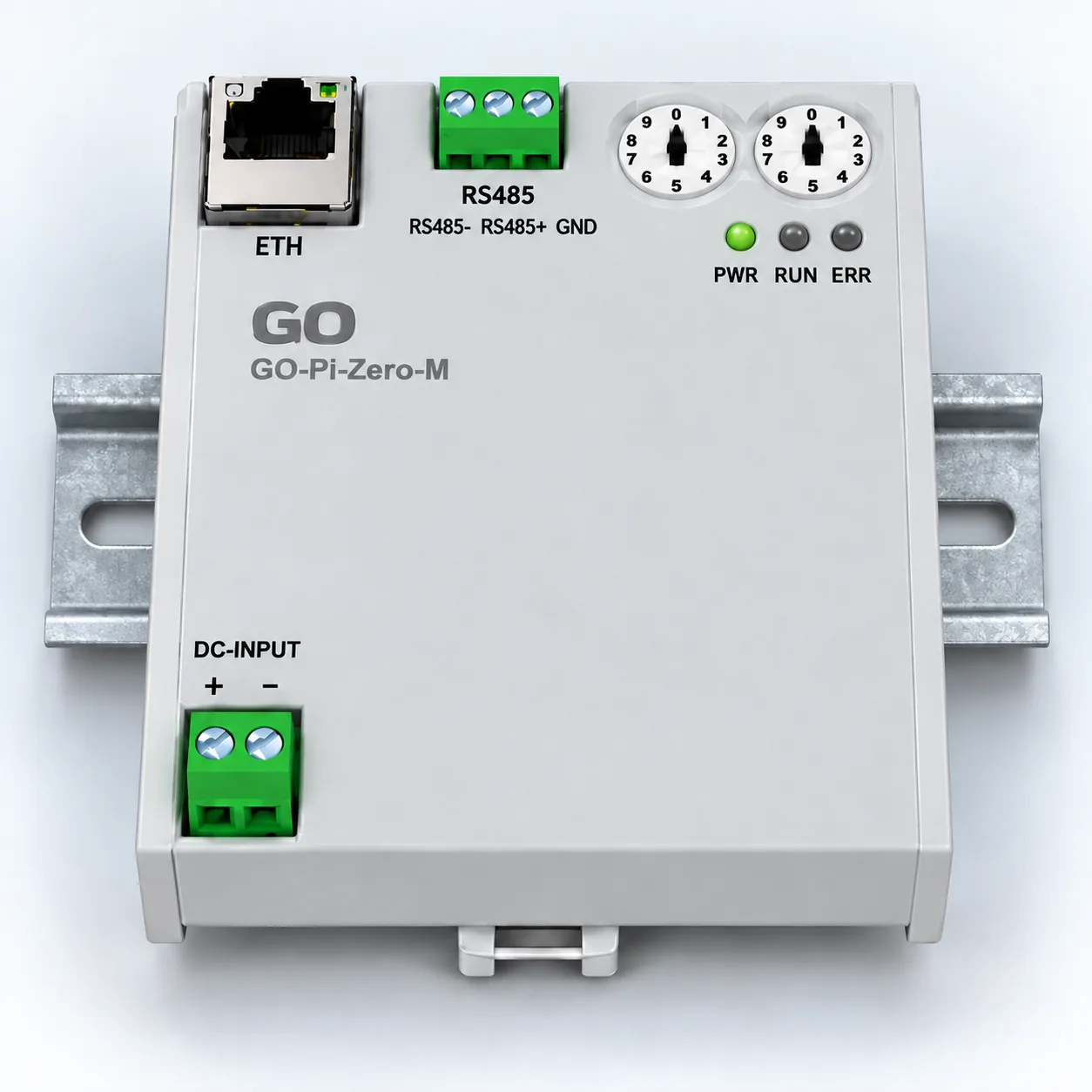
The front face with the cover on: Ethernet (ETH), the 3-pin RS-485 terminal, two rotary address switches, three status LEDs, and the 2-pin DC input at the bottom.
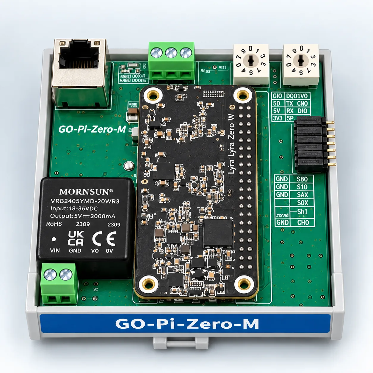
The board inside. Treat the silkscreen text in this image as indicative; the specifications below come from the design file.
Three buses
| Bus | Parts | Connects to |
|---|---|---|
| Ethernet | W5500 + RJ45 | the system above, the site network |
| CAN | MCP2515 + SN65HVD230 | the sub-modules beside it |
| RS-485 | MAX485 | field instruments, drives |
Compute sits on a 40-pin header. It is a Pi Zero form-factor position, so a module of the same shape can be swapped in. The one fitted here is a Luckfox Lyra Zero W.
We picked it while looking for a replacement after the Raspberry Pi Zero 2 W went out of
stock, and both the evaluation and
the benchmark were run on this carrier.
The kernel rebuild described there was to bring this board’s W5500 and MCP2515 up as
eth0 and SocketCAN.
Each bus goes somewhere different. Ethernet goes up, CAN goes sideways, RS-485 goes out to the field. Where the isolation goes follows from that.
Isolation goes on the lines that leave
The RS-485 port floats completely.
B0505S-1WR2   isolated DC-DC  -> creates the isolated rail CH1_5V / CH1_GND
MAX485        RS-485          -> runs entirely on the isolated side
6N137 x2      optocouplers    -> transmit and receive cross separately
TVS x2                        -> protection referenced to the isolated ground
Power is lifted by an isolated DC-DC and the signals cross through two optocouplers, one for transmit and one for receive. A different ground potential at the field device, or a surge coming back down that cable, does not reach the logic here.
The input supply is isolated too. The VRB2405YMD-6WR3 that steps 24 V down to 5 V is
rated for 1500 VDC isolation, so the incoming field 24 V and the board logic already float
relative to each other.
| Line | Goes to | Isolation |
|---|---|---|
| 24 V input | field supply | isolated DC-DC (1500 VDC) |
| RS-485 | field devices | isolated DC-DC + optocouplers |
| Ethernet | network above | transformer inside the RJ45 |
| CAN | modules beside it | same enclosure, same ground - not isolated |
Everything that touches the outside floats; only the CAN that stays inside the enclosure does not. The decision was not about spending parts, it was about which line is dangerous.
Power
24 V in  ->  VRB2405YMD-6WR3 (isolated 6 W, 5 V 1.2 A)  ->  +5V
                              LD1117S33                 ->  +3V3
                              B0505S-1WR2 (isolated)    ->  CH1_5V (RS-485 only)
+5V and +3V3 both go out on the module bus. Sub-modules take that supply and regenerate
their own rails locally.
The address is set by hand
There are two rotary switches. Four bits each, eight wires going straight to the compute module’s GPIO with no expander in between.
Each switch holds one digit, so two dials set a two-digit station number. The address can be changed in the field without a laptop, and the setting stays physically visible on the board.
Protection and signal handling
- Four
P6KE8.2CATVS — surge protection on the lines that leave the board - Varistor and common-mode choke — noise handling at the power input
- Three
BSS123— level shifters taking the compute module’s 3.3 V I2C to the module bus
The compute side runs at 3.3 V while the module bus may sit at a different level, so a
single-MOSFET bidirectional level shifter is fitted on each of SDA, SCL and RESET.
Specifications
| Item | Value |
|---|---|
| Size | 75.0 × 81.5 mm |
| Layers | 4 |
| Parts | 170 |
| Nets | 116 |
| Input | 24 V (18–36 VDC), isolated 6 W |
| Buses | Ethernet · CAN · RS-485 |
| Address | 2 rotary switches (2 digits) |
| Module bus | one 16-pin connector |
Part 3 looks at the three sub-modules that attach beside it.
🔧 GO Modular IO series: Part 1 — the system · Part 2 — the main module · Part 3 — the three sub-modules · Part 4 — specs and expansion
Contact
- Email: [email protected]
- Instagram: https://www.instagram.com/going.sen/
- Website: https://intosen.com/kr/consult/
Comments
Enter a nickname to leave a comment, or sign in with Google or GitHub.