
A record of designing and generating four genuinely usable 3D-printed enclosures in a single session with Claude Code and Blender MCP.
- Tools: Blender 5.1 + BlenderMCP addon + Claude Code superpowers skills
- Workflow: brainstorming → writing-plans → subagent-driven-development
- Output: three finished designs plus one learning case — smart-farm misting nozzle · Arduino Mega + L298P case · 5-inch LCD + Pi + relay shield case · Raspberry Pi 4B case
- The three finished STLs passed manifold verification and are ready to print on an FDM machine (PETG/PLA)
The tool stack — Blender MCP and Claude Code
1. Blender 5.1 + BlenderMCP
Install the BlenderMCP addon into Blender 5.1 and you can send Python from outside to create and edit meshes. In this work we called the bpy API from a Claude Code session through the mcp__blender__execute_blender_code tool.
[Claude Code session] ──MCP/JSON over TCP:9876──> [Blender + BlenderMCP addon]
                                                    bpy.ops.* (primitives, booleans, STL export)
2. Claude Code superpowers skills
Three skills used in sequence:
brainstorming         → requirements interview + design options + spec document
   ↓
writing-plans         → implementation plan (broken into 8-9 tasks, TDD style)
   ↓
subagent-driven-development → a fresh subagent per task, two-stage review
Every project repeats the same pattern. The spec and plan documents are committed to git alongside the code, so later dimensional changes have a single source to refer back to.
3. A proven module pattern
Every case project shares the same file structure:
project/
├── docs/
│   ├── specs/YYYY-MM-DD-<name>-design.md
│   └── plans/YYYY-MM-DD-<name>.md
├── src/
│   ├── params.py     # every dimension (single source of truth)
│   ├── geom.py       # shared Blender helpers (clear_scene, add_cube, add_cylinder, boolean_*)
│   ├── <component>.py # each part (shell, lcd_mounts, cutouts, ...)
│   ├── verify.py     # bbox + non-manifold edge verification
│   └── build.py      # orchestrator + STL export
└── output/
    └── *.stl, *.png  # printable STL + visual verification renders
Edit params.py alone and an immediate rebuild produces new STLs. Dimensional adjustment is extremely flexible.
Project 1: 🌿 Halo spray nozzle (smart-farm misting ring)
Overview
The Halo spray nozzle is a 360° inward-spraying ring that fits a 5 V DC water pump and 6 mm ID silicone hose. It is meant for even watering of a plant’s root zone.
Key design decisions
- Halo shape: six nozzles on the inner rim of a donut disc, spraying inward
- Optimized for a low-pressure 5 V pump: six nozzles (not many) × Ø1.5 mm (less clogging), with a channel cross-section 4.5× the combined nozzle area (minimal pressure loss)
- Nozzles tilted -15° down: water goes to the soil, not the leaves
Cross-section
                  ┌─ barb (pushes 6mm into the hose)
                  │   8mm / 7.5mm two-step barb
                  ▼
              ━━━━━┓
        ┌──────────┻──────────┐
        │  ┌────────────────┐ │  ◀── flat disc (90mm inner bore)
        │  │  ●  ●  ●  ●  ● │ │  ◀── 6 nozzles on the inner rim (60° apart)
        │  │  ●         ●   │ │
        │  │    ┌──────┐    │ │
        │  │    │plant │    │ │
        │  │    └──────┘    │ │
        │  │  ●         ●   │ │
        │  │  ●  ●  ●  ●  ● │ │
        │  └────────────────┘ │
        └─────────────────────┘
        ◀────── 114mm outer ──────▶
Dimensions
| Item | Value |
|---|---|
| Outer × inner × height | 114 × 90 × 10 mm |
| Nozzles | 6 × Ø1.5mm, -15° tilt |
| Barb | 8/7.5/8mm two-step, 15mm tall |
| PETG, 100% infill, ~1.5 hours |
Renders
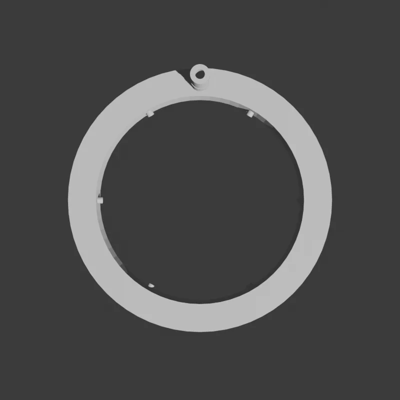 Top view: donut shape, barb at 12 o’clock, six nozzles on the inner rim
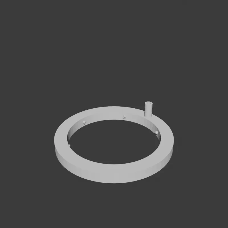 The shape in three dimensions
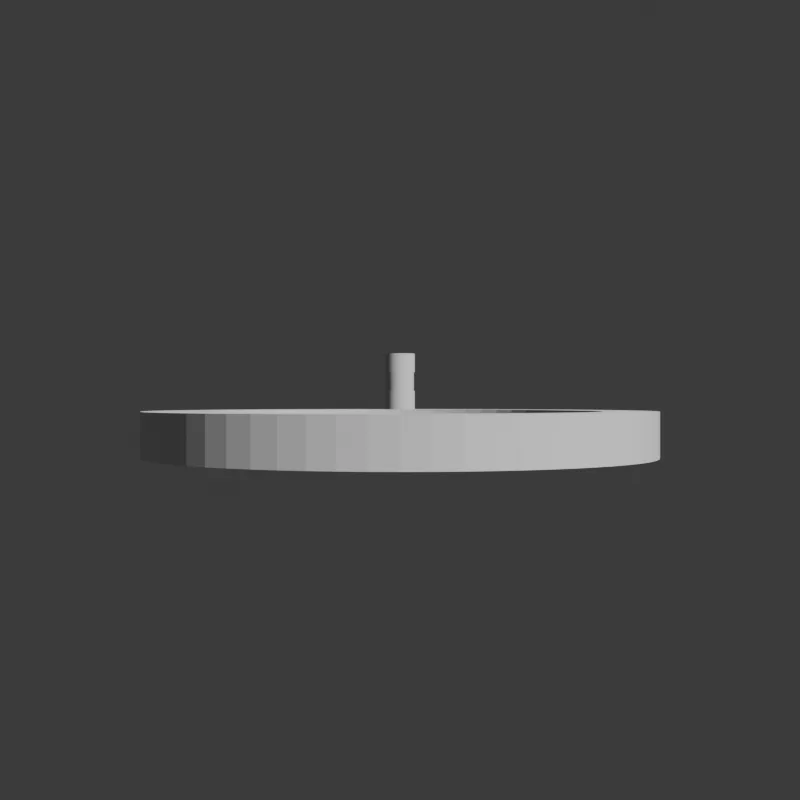 Side view: disc with the barb protruding
STL
halo-nozzle-v1.stl (200 KB)
Project 2: 🔋 Arduino Mega + L298P motor shield case
Overview
The Arduino Mega case is a top-open tray holding an Arduino Mega 2560 with an L298P H-bridge motor shield (Uno footprint). We left the top completely open for free access to the jumper headers on the shield.
Key design decisions
- Single monolithic tray (fully open on top): jumper access plus free access to the Mega’s D22–D53 headers
- 4× M3 standoff bosses: exact mapping of the Mega PCB’s four mounting hole coordinates (15.24 / 50.8 / 96.5 and so on)
- Side-entry motor terminals: the L298P shield’s motor cables pass through the side wall
- 11 vent slits (5+6): a grid pattern on the short side and the long side
- USB-B + DC jack cutouts: on the Mega’s short edge
Correction history (driven by boxes drawn on the user’s photos)
| Version | Change |
|---|---|
| v1 (wrong) | USB-B and DC jack positions mirrored |
| v1 fix | USB/DC coordinates swapped |
| v2 fix | Motor cutout moved to a different face (long side 1 → long side 2) and vent slits rearranged |
→ A box drawn on a photo is the most accurate information available. No guessing.
Dimensions
| Item | Value |
|---|---|
| Outer (W × D × H) | 111 × 63 × 35 mm |
| Standoffs | M3 × 4, Ø6/Ø2.5, 5mm tall |
| Cutouts | USB-B + DC jack + motor cable + vent slits |
| PETG, 4 walls, 25% infill, ~3.5 hours |
Renders
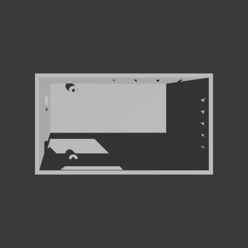 Top view: tray, four corner bosses, side cutouts
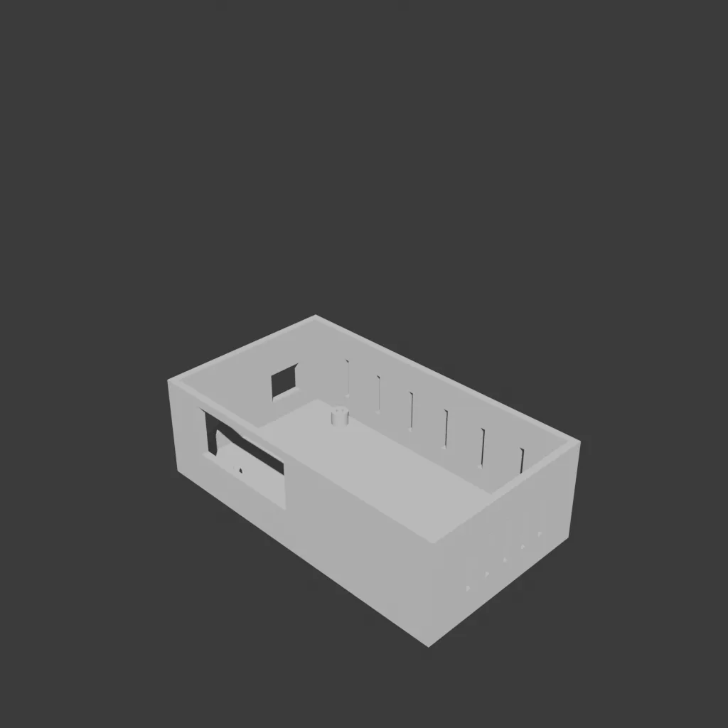 In three dimensions (v2, after corrections)
STL
mega-l298p-case-v1.stl (138 KB)
Project 3: 📺 5-inch DSI LCD + Pi 4 + relay shield case (a learning case)
Overview
The 5-inch DSI LCD case is a landscape enclosure holding a Waveshare 5inch DSI LCD (B), a Raspberry Pi 4, and a Pi-Sd8R relay shield (four PA1A relays plus a MAX485).
Design decisions and seven rounds of correction (by far the most trial and error)
| Version | Change |
|---|---|
| v1 | Portrait orientation, Pi USB facing down |
| v2 | Rotated to landscape, cutouts remapped (12-pin terminal and Pi USB positions corrected) |
| v3 | Mounting pins → internal boss columns (retention method corrected) |
| v4 | Removed an unnecessary cable pass-through slot |
| v5 | Detailed STEP analysis, outer shell reduced, Pi USB cutout in the back panel |
| v6 | Back panel closed, Pi USB moved to the left side |
| v7 | Split into two pieces (LCD frame + Pi case) |
| v7.2 | Measured LCD dimensions applied (bezel 128×82, PCB 122×76) |
| Stopped | The essential structure (clamshell joint / Pi access / LCD mounting) stayed ambiguous, so we decided to start over |
The most important lessons
- Parse STEP/CAD files precisely from the start: be clear about whether an R=4 corner circle is a “corner round” or the “board edge”
- The user’s measurement beats the datasheet: a difference between bezel and PCB size has to be measured
- Fix the essential structure first:
- LCD mounting direction (screws from the front, back, or side?)
- The Pi 4’s USB jacks sit inside the LCD outline, so a single-piece case cannot have a side cutout for them (the LCD standard has the Pi hanging on the center of the LCD’s back)
- How the parts separate and join
- In a two-piece design, make the joining method explicit (snap / screw / press fit)
STEP data extracted through detailed analysis
LCD outline (R=4 corner circles + z=-1.7 outline):
  127.7 × 87.4 mm (corner R4)

LCD mounting holes (Ø2.0):
  (±56.5, ±32.9) from the LCD center
  → inset from the edge: X=7.35, Y=10.8 mm (asymmetric)

Pi 4 mounting holes (LCD back side):
  (-32.5~25.4, -23.8~25.3) from the LCD center
  → standard Pi 4 58×49 pattern, offset -3.55mm in X
Conclusion
This project taught us that starting from the outer shell without deciding the essential structure leads to endless corrections. We decided to start over from scratch.
Project 4: 🐰 Raspberry Pi 4B standalone case
Overview
The Raspberry Pi 4B case is a standard clamshell, done correctly from the beginning using what the LCD case taught us. No GPIO in use, so a closed top was acceptable.
Key design decisions (passed in one attempt, no corrections)
- Clamshell: body tray plus top lid, joined by four M3 corner screws
- Every port exposed: USB-C + 2× microHDMI + AV (short side 1), 4× USB + Ethernet (long side), microSD (short side 2)
- Passive ventilation: 12 rectangular slits in the top lid (a 4×3 grid)
- Desk friendly: Ø8 × 0.5 mm rubber foot recesses at the four base corners
Cross-section
   ┌─────────────────────────────────────┐
   │  ┌─┐ HDMI HDMI ┌─┐  ┌─┐  USB-C      │  ← top lid (z=25~30, 5mm thick)
   │  │ │  □   □   │ │  │ │  □           │     12 vent slits
   │  └─┘                                │     4 corner through-holes
   ├─ ▒▒▒▒▒▒▒▒▒▒▒▒▒▒▒▒▒▒▒▒▒▒▒▒▒▒▒▒▒▒▒▒▒ ─┤  ← clamshell joint (z=25)
   │  ◯ 4× Pi 4 mounting bosses      ◯   │  ← body (z=0~25)
   │     (Pi standard 58×49 pattern)     │
   │                                     │     side-wall cutouts:
   │  ◯                              ◯   │     USB + Ethernet (long side)
   │ ▓▓▓▓▓▓▓▓▓▓▓▓▓▓▓▓▓▓▓▓▓▓▓▓▓▓▓▓▓▓▓▓▓▓▓ │     USB-C/HDMI/AV (short side)
   └─────────────────────────────────────┘     microSD (other short side)
   ◀────── 92mm ──────▶
Dimensions
| Item | Value |
|---|---|
| Outer (W × H × D) | 92 × 62 × 30 mm (body 25 + lid 5) |
| Pi mounting | 4× M2.5 bosses (Pi standard 58×49) |
| Clamshell joint | 4× M3 bosses (corners) + Ø3.2 through-holes in the lid |
| PETG, 4 walls, 25% infill, body ~2h + lid ~1h | |
| Mesh | manifold ✅ (body 0, lid 0) |
Renders
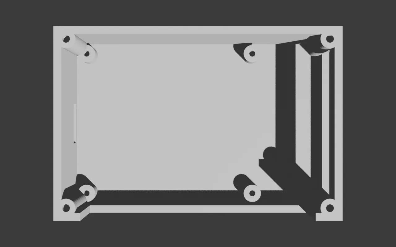 Body from above: four corner clamshell bosses, Pi mounting bosses in the middle, side cutouts
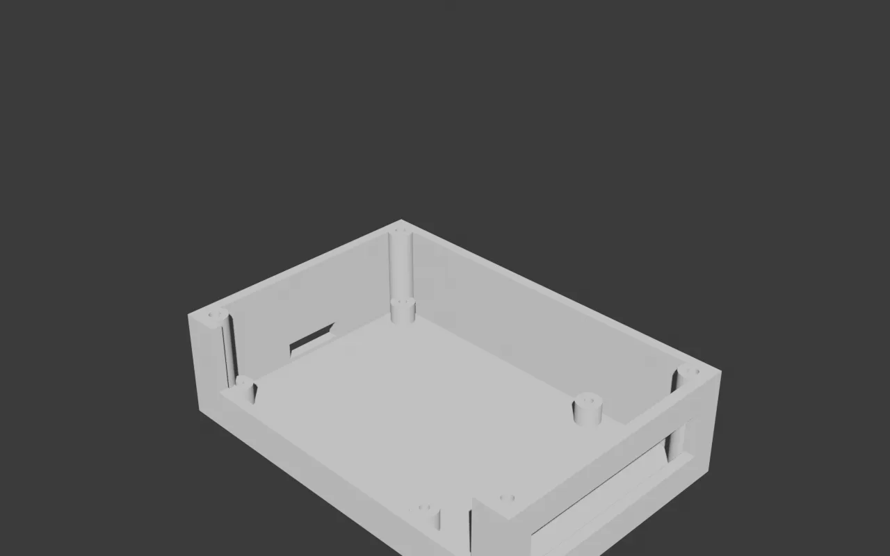 The body in three dimensions
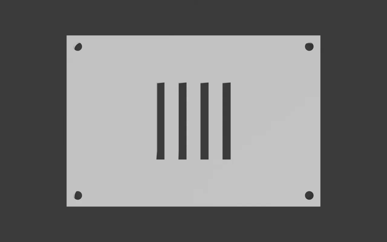 Lid from above: four corner through-holes and a 12-slit vent grille
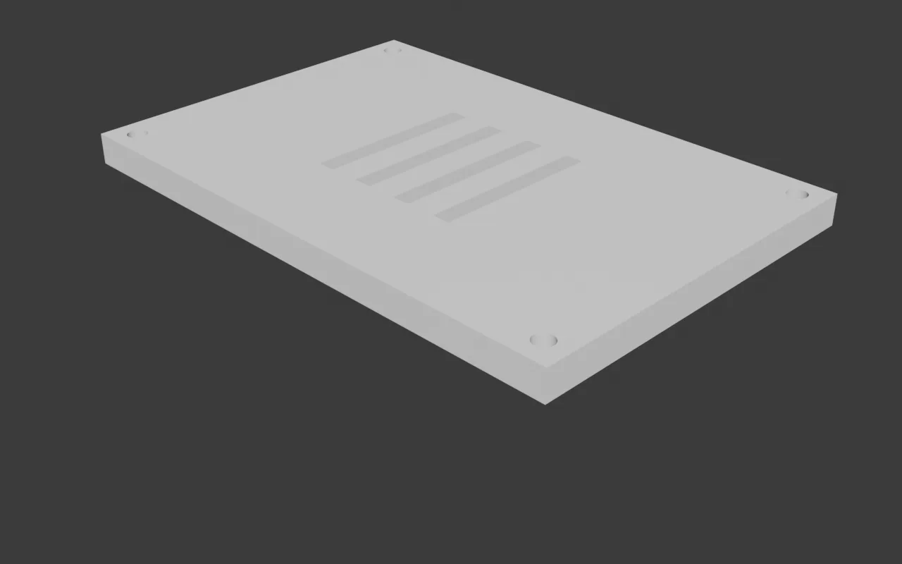 The lid in three dimensions
STL
pi4b-case-body.stl(193 KB)pi4b-case-lid.stl(51 KB)
A reusable Blender MCP design workflow pattern
1. Brainstorming stage
user requirements come in
  ↓
one multiple-choice question at a time
  - case type? (tray / clamshell / slide)
  - which ports exposed? (multiple choice)
  - mounting method?
  - how is it placed?
  - cooling?
  ↓
2-3 proposed approaches with trade-offs
  ↓
design section presented (dimension table + ASCII diagram)
  ↓
spec document written + self review
  ↓
user review gate
2. Writing-plans stage
The spec is broken into seven to nine tasks:
Task 1: params + geom + git init
Task 2: shell (outer box)
Task 3: mounting bosses (boss columns)
Task 4: cutouts (port cutouts)
Task 5: verify (manifold + bbox)
Task 6: build orchestrator + STL export
Task 7: visual verification (renders from several angles)
Task 8: README (print and assembly guide)
Each task is a single action of two to five minutes, and carries complete code blocks with no placeholders.
3. Subagent-driven-development stage
A fresh subagent is dispatched for each task, followed by a two-stage review (spec compliance and code quality). No context contamination.
What 3D case design taught us (to apply next time)
✅ What worked
- params.py as the single source: dimensions defined once, imported by every module. One place to change.
- Reusing a proven module pattern: boilerplate like geom.py / verify.py / build.py gets copied into each project, saving infrastructure time.
- The subagent workflow: four projects (30+ tasks total) finished in one session with no context explosion.
- Automated visual verification: a Blender render after every build to check the shape. Design review is possible even with no board connected.
❌ What to avoid
- Designing from estimated values: on the LCD case we estimated the outline from the first 50 lines of the STEP file, missed by 5 mm, and paid for it with seven corrections.
- Starting from the outer shell without the essential structure: if the joining method and mounting direction are vague, a correct outline still ends in a redo.
- Ignoring the user’s measurements: when two sizes differ — bezel 128 vs PCB 122 — the one the user measured with a ruler is the right one.
- A single-piece case with Pi USB exposed on the side: if the Pi hangs on the back of the LCD, its USB jacks are always inside the LCD outline, so a side cutout is impossible. That kind of intrinsic constraint has to be known up front.
3D printing settings (common to every project)
| Item | Value |
|---|---|
| Material | PETG (first choice, heat and wear resistance) / PLA acceptable |
| Nozzle | 0.4 mm |
| Layer height | 0.2 mm |
| Wall lines | 4 |
| Top/bottom | 4 lines |
| Infill | 25% (100% for the Halo) |
| Supports | none (no design needs them) |
Code example: every dimension managed in params.py
"""Pi 4B Case dimensions (all in mm)."""

# Pi 4 standard
PI_PCB_W = 85.0
PI_PCB_H = 56.0
PI_MOUNT_HOLES_PCB = [
    (3.5, 3.5), (61.5, 3.5), (3.5, 52.5), (61.5, 52.5),
]

# Case outline (Pi + walls + margin = computed automatically)
WALL = 2.5
PI_BOARD_MARGIN_X = 1.0
OUTER_W = PI_PCB_W + 2 * (WALL + PI_BOARD_MARGIN_X)  # 92.0

# Mounting bosses (case coordinates = PCB position + standard hole coordinates)
PCB_ORIGIN_X = WALL + PI_BOARD_MARGIN_X  # 3.5
PI_BOSS_BL = (PCB_ORIGIN_X + PI_MOUNT_HOLES_PCB[0][0], ...)  # (7.0, 6.5)

# ... every cutout, boss, and vent lives in this one file
Change a dimension, call build.main() once, and new STLs appear.
Wrapping up — four cases designed in a day
The combination of Claude Code and Blender MCP let us take four cases from design to print-ready in a single day. The seven rounds of correction on the LCD case were what made the Pi 4B case pass on the first attempt.
Lessons from building 3D-printed enclosures:
- Work in the order essential structure (mounting, joining, port exposure) → outer dimensions → cutouts
- Measurements first, guessing never
- A single source of truth (params.py) cuts the cost of every correction
Next up: an ESP32 case, a DIN-rail mount converter case, and a VESA-mount media PC case.
Keeping every dimension in params.py and using measured values instead of estimates was the surest way to cut the number of corrections.
Contact
- Email: [email protected]
- Instagram: https://www.instagram.com/going.sen/
- Website: https://intosen.com/kr/consult/
Comments
Enter a nickname to leave a comment, or sign in with Google or GitHub.