
Why we built a low-cost PLC alternative
Industrial PLCs are everywhere in industry. Mitsubishi, Siemens, Rockwell — all of them stable, all of them proven. And yet a single PLC for a small control job runs about 300,000 KRW. Add the cabling, a communication module and the programming software and 500,000 KRW goes past very easily.
For small automation jobs, training rigs, R&D prototypes and maker projects, that is too expensive and too closed an ecosystem. Speaking Modbus means buying an extra RTU/TCP slave module. Sending data to a cloud means bolting on a separate gateway.
That is why we built ZPi Controller. The combination is a Raspberry Pi Zero 2 W, a 4-input/4-relay board, .NET 9 and Blazor:
- Hardware: around 50,000 KRW (Pi Zero 2 W + ZPi-IO08R board)
- Software: open
- Communication: Modbus TCP/RTU slave and master, MQTT planned
- Programming: a web browser is all you need
- UI: a full-screen HMI the AI writes for you (see the next post)
ZPi Controller hardware and software layout
[Raspberry Pi Zero 2 W]
    │
    ├─ ZPi-IO08R board (4DI opto-isolated + 4DO relay)
    ├─ 0.96" OLED (IP + time + IO, optional)
    └─ I2C / SPI / UART (expansion)

[.NET 9 service (systemd)]
    ├─ Blazor WebAssembly admin UI (port 5000)
    ├─ Modbus TCP slave (port 502)
    ├─ Modbus RTU master/slave (RS-485)
    ├─ Rule engine (50ms tick) — matrix + natural-language cards + Python code
    └─ MCP server (Claude Desktop / Code integration)
ZPi Controller feature set at a glance
| Page | What it does |
|---|---|
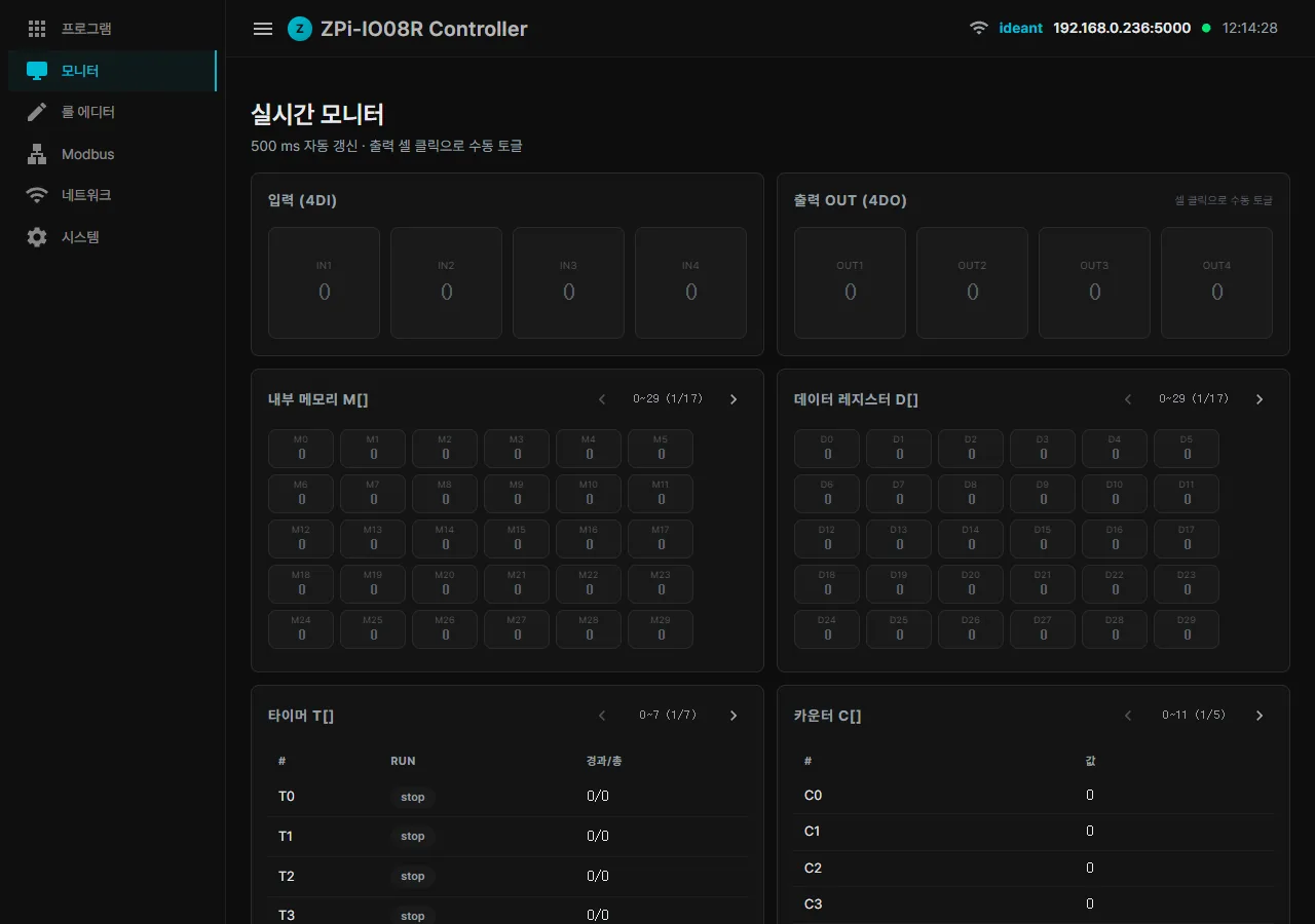
| Monitor | Live view of inputs, outputs, memory, timers and counters |
| Rule editor | Input-to-output matrix + extra rules in plain language + advanced Python (Tick()/OnInput()) — all three share one variable pool |
| Modbus | TCP slave / TCP master (polling external slaves) / RTU slave / RTU master, configured in one place |
| Network | WiFi scan, connect and auto-restore, hostname change (mDNS) |
| Programs | Upload, run and auto-start user .NET, Python or native programs |
| System | OS, memory, temperature and IP, password change, one-click MCP install |
| ZView (added in this round) | Full-screen operator HMI, generated by AI from a plain-language request |
Rule editor — three ways to write logic on one screen (v2)
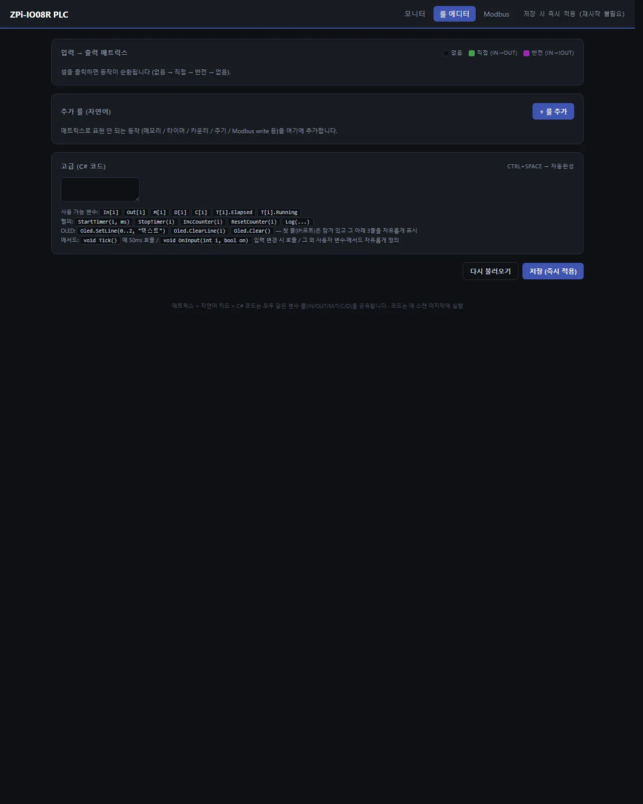
The browser rule editor offers three ways to write a rule, and all three share the same variable pool (IN/OUT/M/T/C/D) and run together at the end of every 50ms scan.
- Input-to-output matrix — clicking a cell cycles through
none → direct (IN→OUT) → inverted (IN→!OUT). Straight-through wiring is done without a single line of code. - Extra rules in plain language — anything the matrix cannot express (memory, timers, counters, periodic actions, Modbus writes) is stacked up as cards with ”+ Add rule”.
- Advanced Python — when that is still not enough, write it yourself. Logic goes into the
Tick()entry point (every 50ms) orOnInput(i, on)(on an input change).
What Python code can reach directly:
- Variables:
In[i]·Out[i]·M[i]·D[i]·C[i]·T[i].Elapsed·T[i].Running - Helpers:
StartTimer(i, ms)·StopTimer(i)·IncCounter(i)·ResetCounter(i)·Log(...) - OLED:
Oled.SetLine(0..2, "text")·Oled.ClearLine(i)·Oled.Clear()
So “turn OUT0 on when IN0 comes on, then OUT1 one second later” looks like this:
void Tick()
{
    Out[0] = In[0];
    if (In[0] && !T[0].Running) StartTimer(0, 1000);
    Out[1] = T[0].Elapsed >= 1000;
    Oled.SetLine(0, $"IN0={In[0]}  OUT1={Out[1]}");
}
Cover 80% with clicks in the matrix and push only the complicated remainder into cards and Python — that is the direction of the v2 rule editor.
Modbus TCP and RTU communication
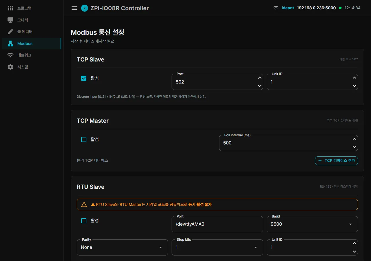
- TCP slave (port 502) — an external SCADA or HMI polls this board
- TCP master — this board polls other Modbus TCP slaves and maps them into the
D[]registers - RTU slave (RS-485) — the same memory map exposed over RS-485
- RTU master (RS-485) — polls external RTU slaves
The memory map:
P(Coil) — outputsM(Coil) — internal bitsT(Holding) — timer ElapsedMs/100C(Holding) — countersD(Holding) — data registersWp/Wm— bits packed into words
WiFi dropouts and boot delays — network self-healing
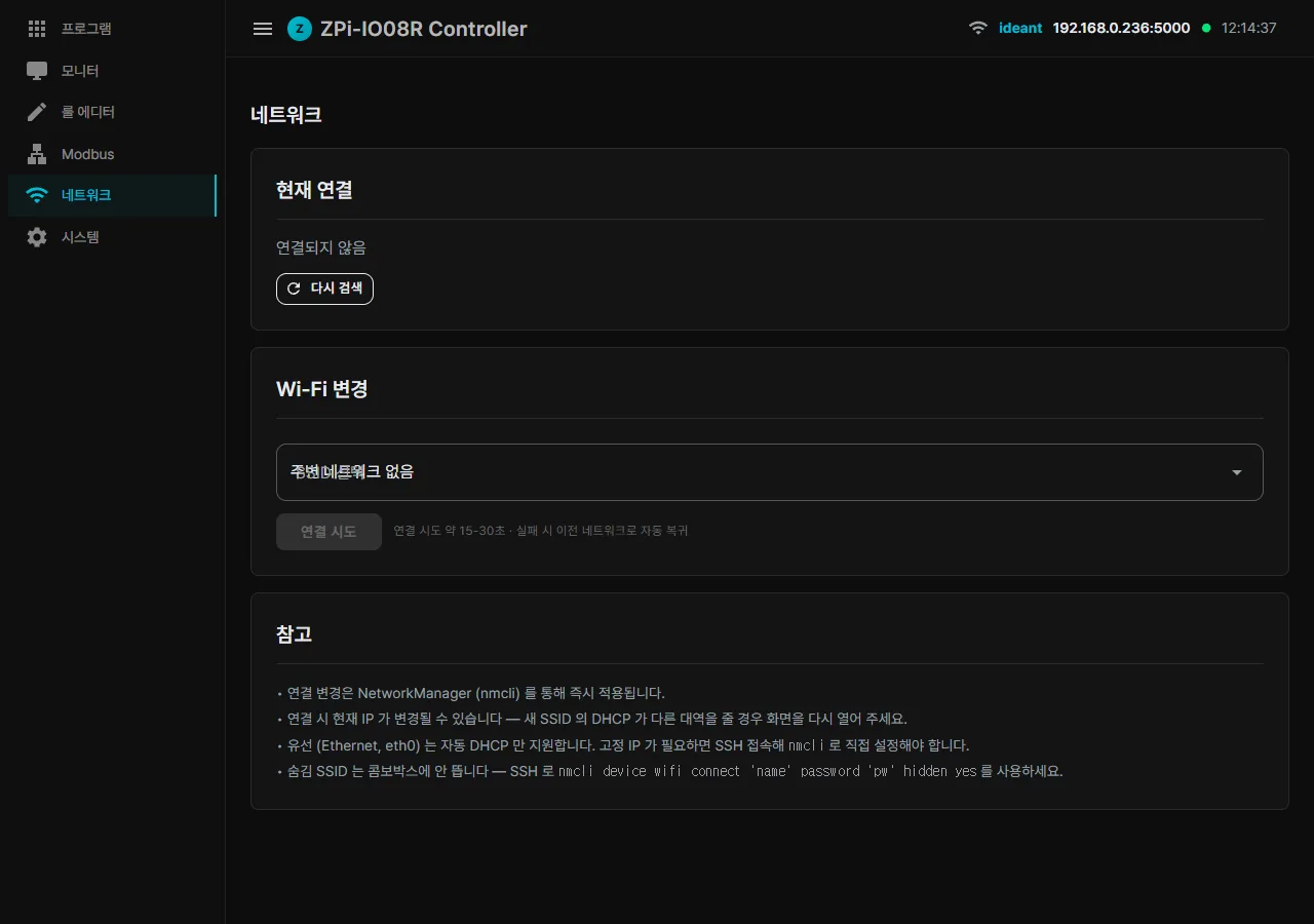
Raspberry Pi WiFi dropping out is genuinely infuriating. NetworkManager profiles disappear (especially after cloning an SD card), DHCP hands out a new IP and confuses mDNS, or boot time stretches out to a minute and a half.
We fixed all of it this round — part 5 of this series has the detail.
Programs — hosting user code
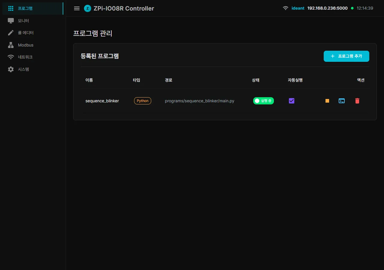
Hosting user code follows the LauncherTouch style: you upload a zip containing a self-contained .NET executable, a Python script or a native binary, and the board runs it like a systemd companion service. Auto-restart, auto-start and log viewing are all supported. GPIO ownership is arbitrated by EngineGate, which hands control back and forth between the rule engine and the user program automatically.
System page and the Claude MCP integration
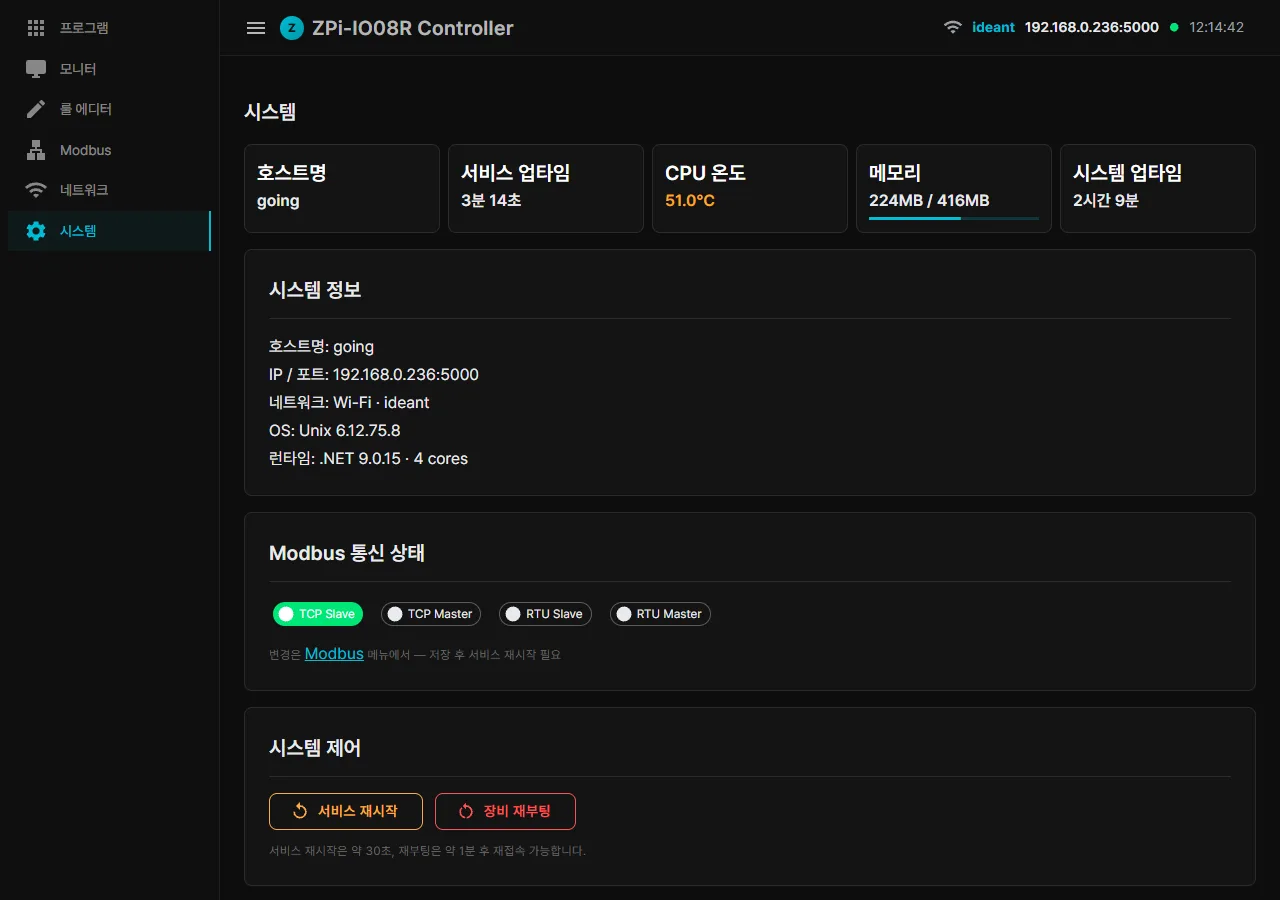
Claude MCP integration takes a single button. Press “Install MCP (PC integration)” on the system page and a Windows BAT file downloads. Double-click it and the MCP server registers itself with both Claude Desktop and Claude Code.
Note: boards ship with default passwords already set for the operator and admin accounts (the values are in the manual that comes with the board). Change them before putting the board into service.
This is the most interesting part of the whole thing. The AI can drive the PLC directly and, beyond that, build and deploy an operator HMI page. The next post covers it in detail.
What comes next in the ZPi Controller series
- Part 2 — ZView: the operator HMI that AI builds
- Part 3 — the one-double-click MCP installer for Claude Desktop
- Part 4 — three gotchas we debugged (Modbus, mDNS, regex)
- Part 5 — WiFi auto-recovery and boot time from 1 min 31 s down to 33 s
- Part 6 — what comes next (MQTT, WebSocket, alarms)
A Raspberry Pi Zero 2 W and a 4-input/4-relay board are enough to build a PLC with Modbus slave and master and a browser rule editor.
Contact
- Email: [email protected]
- Instagram: https://www.instagram.com/going.sen/
- Website: https://intosen.com/kr/consult/
Comments
Enter a nickname to leave a comment, or sign in with Google or GitHub.