
In part 8 we wrote that the io16 four-layer board was done. Then a review started - zooming into the actual drawings one sheet at a time - and that is where the real gaps in the automation appeared. This installment is not a success story. It is a record of why the things we believed had passed had not passed.
One-sentence summary
The metrics we measured passing is no evidence whatsoever that the items we did not measure are correct.
1. “An IC with no legs” - the symbol had artwork but no pins
KiCad symbol pins were the first note: why does the IC have no legs?
Symbols converted from PADS decals had pin length 0 across the board. What looked like legs were the decal’s slanted lead graphics, and the fan-shaped spread came from the same cause. ERC does not catch this - the connections themselves are fine.
The fix was to delete the decal graphics and build real KiCad pins:
- Remove the polylines (leads) touching the pins, and decorative art outside the pin bounding box
- Inject a new body rectangle at the standard inset, 3.81mm back from the pins and 2.54mm top and bottom
- Pin angle = direction of the body, length = actual distance to the body
Once the legs appeared there was a side benefit. The O marker at the end of an unconnected pin becomes visible, so connectivity can now be checked straight off the drawing.
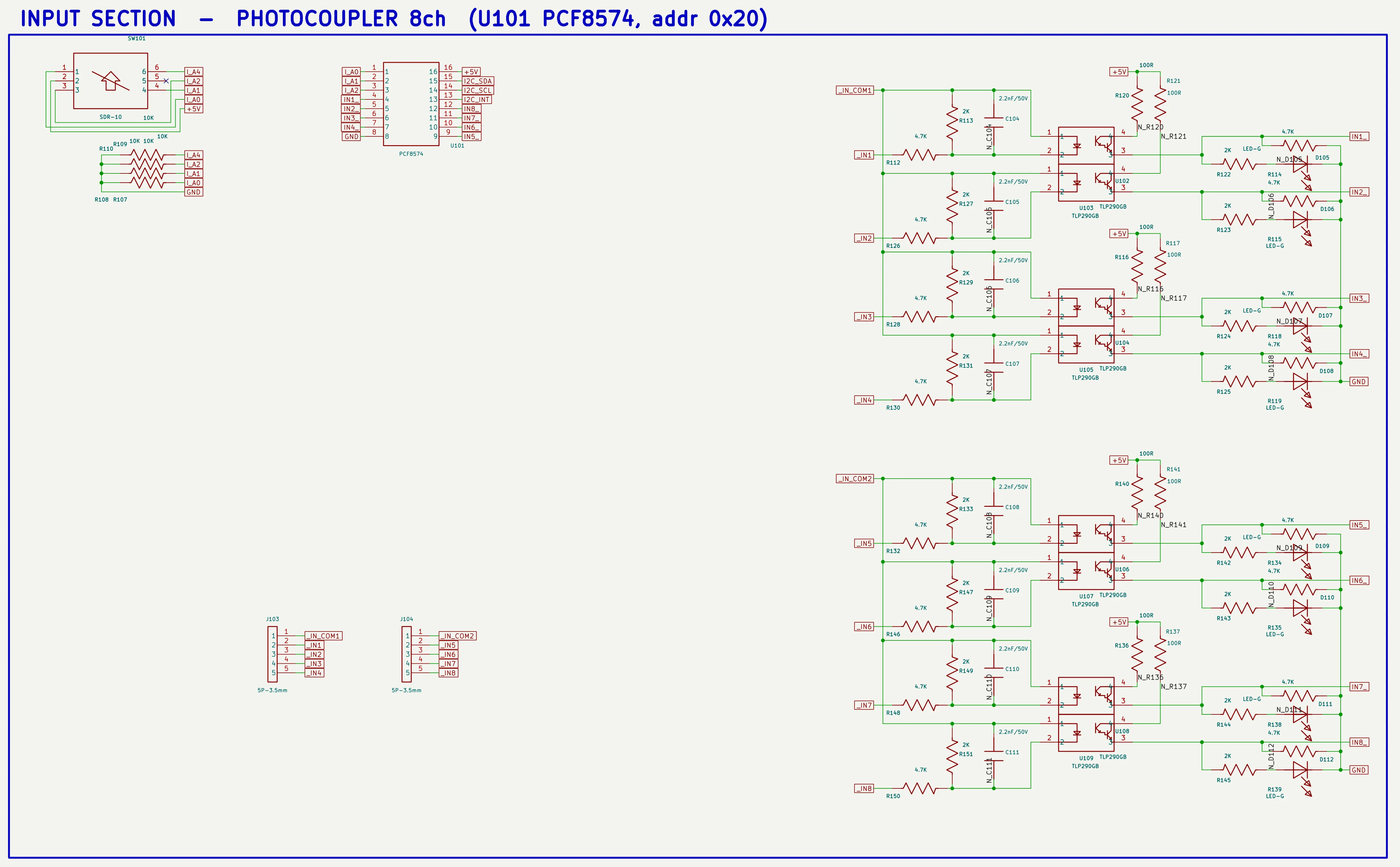
The input section after the fix. The ICs and optocouplers have legs, and pin numbers and names sit outside the body. Only in this state can you visually confirm that the eight channels repeat in the same shape - without legs this drawing was just a row of rectangles.
One trap: if the leg direction is taken as “toward the centroid of the pins”, every pin on a 16-pin IC ends up slanted into a fan. It has to be whichever of the four axes reaches the body first.
2. We redrew the schematic while the PADS original sat right there
The PADS LOGIC original was the second note, and it stung. Reference the existing schematic. Do not draw whatever you like. The PADS schematic is right there - why can you still not draw it the same?
It was a fair point. A PADS LOGIC design export contains all of it: symbol geometry
(CAEDECAL), part placement (PART), wire coordinates (CONNECTION), junctions (TIEDOTS), and
off-page positions (OFFPAGE REFS). The original designer’s drawing could have been carried
over as it was, and instead we were redrawing it with our own placement algorithm - while
overwriting the porting tool (logic2sch.py) we had already built.
Restoring the ported version turned the schematic back into a drawing made by a human. What remained was not “redraw it” but correct only the defects that come from KiCad’s rendering differences.
3. Labels (off-page) - why we repeated the same mistake five times
Off-page label placement was the longest-running problem. Labels covered symbols, lay on their side, and pointed the wrong way. Each time we found them by eye, fixed them, and reported cleanup complete. And then they appeared again in the next zoomed screenshot. The cause was simple - only one thing was being measured.
Label placement has to measure at least four things at once.
Gate 1  label vs symbol body overlap    = 0
Gate 2  label vs label overlap          = 0
Gate 3  vertical (90/270) global labels = 0     <- power labels tipping onto their side
Gate 4  direction compliance            = 100%  <- does it extend along an axis with no wire?
We also learned that getting the measurement model wrong disables a gate entirely.
- Set the global label box height to +/-1.3 and a neighbour on a 100mil pitch (2.54mm) is always computed as overlapping by 0.06mm, which blocks correction forever. The measured value is +/-1.15.
- Local labels are
justify left bottom- the text is drawn above the anchor. Model them as centre-aligned and you will not catch a single overlap on top of a symbol.
The direction rule was wrong twice as well. “Opposite side of the nearest symbol” flips on a two-row connector, and “opposite of the summed wire direction” lies down along the wire at a T junction. The right answer was to quantise each wire direction onto an axis and pick the axis that is empty.
4. Regex edits that fail silently
The relay copper pour was what we were asked to change - keep it on the load side only and restore the supply side - and we made the change. We ran DRC, confirmed it passed, and reported completion. The actual file was untouched.
KiCad 10 writes several zone polygon points on one line, like (xy a b) (xy c d). Our
substitution regex assumed one per line, and even with zero matches the file was rewritten,
so it looked like a success. DRC passed, naturally - nothing had changed.
Two lessons. Cut the block by matching parentheses and replace that, and read the file back after writing to confirm the target value.
5. And angles - what DRC never checks
Trace angles were the last note, and it hurt the most. Who routes a PCB with diagonal lines like this? We said no right angles from the very start.
While building the trace simplification pass, we had put arbitrary-angle straight lines and L-shaped (right-angle) paths into the candidate set. DRC only looks at shorts, unrouted nets, and clearance. It does not look at angles. So it passed.
Only after building a measurement gate did the numbers show up.
segments 1023 : H/V 586 - 45° 429 - arbitrary 8 - right-angle corners 85Those 85 right angles were not the autorouter’s fault. Freerouting defaults to 45 degrees. They came from the finishing passes we ran afterwards - power trunk shoulders, via stitching, L-shaped candidates.
After pulling arbitrary angles and right angles out of the candidate set and rerunning, we built a pass that chamfers right-angle corners to 45 degrees and repeated it. Arbitrary angles went 8 to 4, right angles 85 to 57. We stopped there - at the current routing density, cutting further creates clearance violations and the gate rolls them back automatically. That is the limit of after-the-fact correction. The real fix is a reroute that enforces 45 degrees from the start.
Results after the review
| Metric | Value |
|---|---|
| Schematic ERC / netlist | 0 errors / full match with intent |
| Label and text overlap | 0 on bodies, 0 label-to-label, 0 text |
| Label direction compliance | 197/201 |
| Board DRC | 2 errors, 0 unrouted, 0 shorts |
| Board angles | H/V 591, 45° 468, arbitrary 4, right angle 57 |
| Trace simplification | 62 zigzag chains cleaned up, segments -102 |
| Relay pour | Cut on the contact (load) side only, coil and supply side restored |
What is left - a 45-degree enforced reroute
- A 45-degree enforced reroute - the only way to take those 57 right angles to zero
- Two clearance violations (13µm and 7µm) - solved at the root by +0.3mm of row spacing in the input section placement
- Four label directions - the wire goes left and the label goes right, but on the right is an LED body and the pin opposite blocks even a stub. Left as is, prioritising zero overlap
The rule this part produced (now written into the skill)
Measure the item itself before saying it is fixed. Another metric passing is not evidence.
- DRC does not look at angles, so run a separate angle gate
- Substitutions fail silently, so read back after writing
- Re-measure every metric after the last script in the pipeline (an earlier stage passing means nothing)
- Keep right angles and arbitrary angles out of the finishing candidate set
- A script reporting “0 items processed” is not a success, it is a warning sign (most of the time the conditions were too strict and it did nothing)
The quality of automation comes not from how clever the generator is but from how tight the gates are. This installment is the record of learning that after being hit with it five times.
Measure the item itself before saying it is fixed, and remember that the quality of automation comes from how tight the gates are.
Part 10 follows: before saying it cannot be done. A new board still had unrouted nets. Three times we concluded it was impossible, and three times the tool had simply failed to see the channel.
Parts 1 through 8 are the main series; this piece and the ones after it come out of the review that followed.
Contact
- Email: [email protected]
- Instagram: https://www.instagram.com/going.sen/
- Website: https://intosen.com/kr/consult/
Comments
Enter a nickname to leave a comment, or sign in with Google or GitHub.