
The story so far: a 950-won potentiometer as the lever
The beer game cabinet was already a game cabinet by the end of Part 1. Pull the lever and the glass fills, let go and the verdict lands, finish ten rounds and you carve your initials into the hall of fame. Except that the “lever” was, in reality, a 950-won potentiometer rolling around on the desk. We were discussing “feel” while twisting a bare metal shaft with our fingertips.
Part 2 is therefore about the things you can hold. We built a lever worthy of the name, and while we were at it we got greedy and went after vibration haptics. One of the two worked and one did not, and honestly the failure is the more interesting half.
Whittling a lever - parametric modeling with Blender and AI
The ball-knob operating lever you see all over industrial sites was the reference: a steel rod with a round ball on the end, the kind of thing bolted to the side of a machine that makes you want to pull it. We modeled it by attaching AI to Blender (via MCP) and describing it in conversation. Saying “hub diameter 16, rod 85, ball 24” grows a parametric script, so a dimension change is one line of dialogue.
We split the structure into two pieces.
- The lever: ball, rod, and hub. The hub bore is an interference fit onto the potentiometer’s knurled shaft
- The pillar: a cylinder with the whole potentiometer inside it. Only the shaft protrudes at the front, and the wiring runs through a channel in the body and out the bottom
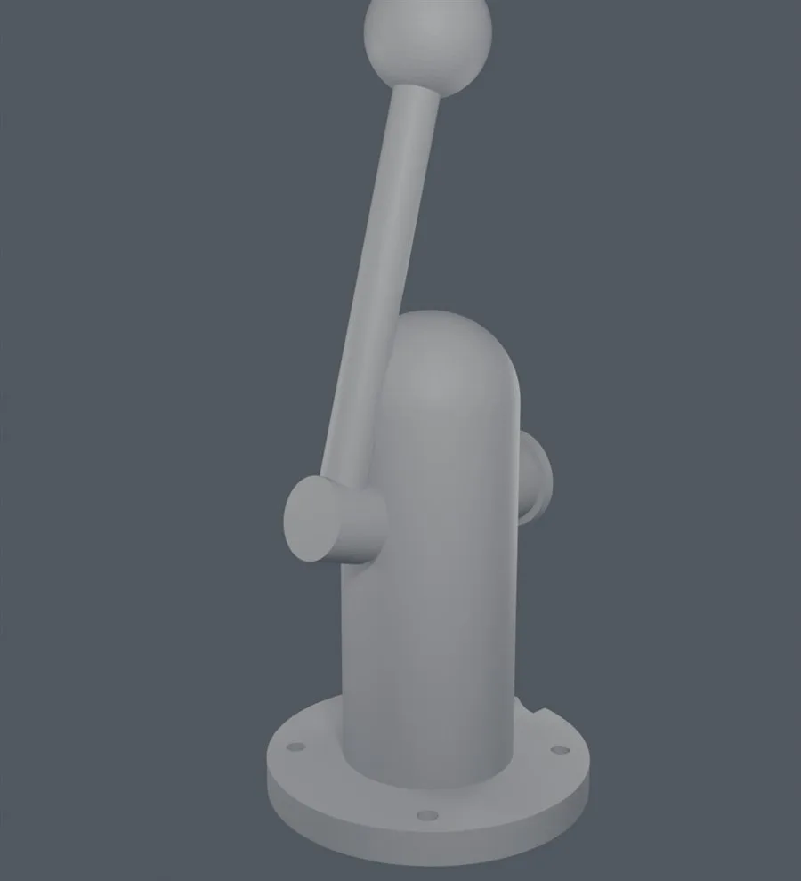
From the outside it is just “a lever on a pillar,” with no electronics visible at all. That was the goal.
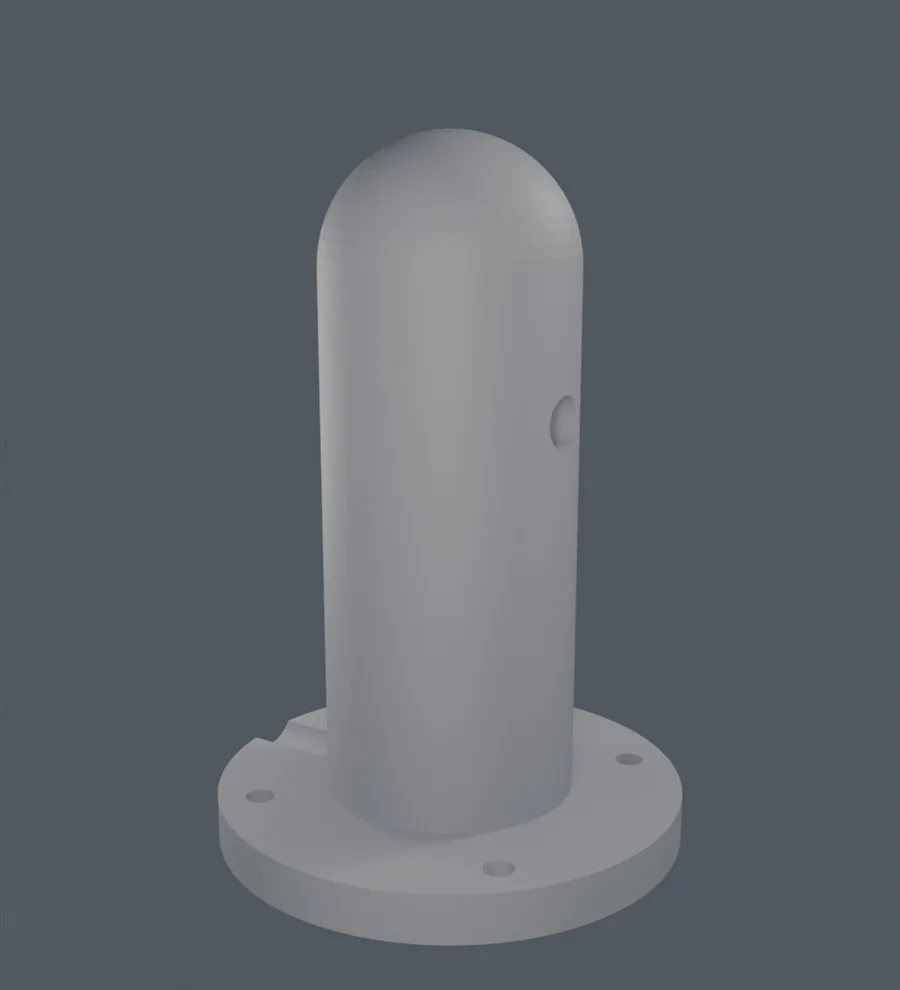
The photo that overturned the design
Up to that point it went smoothly. On paper.
The first design pushed the potentiometer in through a tunnel from the back of the pillar. We measured the pocket diameter and even ran a raycast to verify the wiring channel was clear end to end (on the first attempt there was a 2.5mm wall hiding halfway down the channel - an internal passage you cannot see has to be verified, not assumed).
Then we photographed the actual potentiometer, and everything collapsed.
“So you want me to just cut the potentiometer’s legs off?????”
The potentiometer in the drawing was a well-behaved cylinder. On the real part, the terminal legs splay out wider than the body. It was never going into that tunnel. We redesigned it as a compartment open at the back with a screwed-on cover instead of a push-in tunnel, and put a 45° roof on the compartment ceiling so it prints without supports.
One photo of the real part overturned the design. In 3D modeling, the dimension that matters most is not the one on the screen, it is the one on the part sitting on your desk.
Ready to print
The final set is three files: the ball lever, the pillar (v3), and the rear cover. The mesh was repaired down to zero non-manifold edges and frozen in a state that goes straight into the slicer. A tiny hole was hiding at the joint where the dome meets the cylinder and cost us some time - catching that kind of thing before the slicer is a hundred times cheaper.
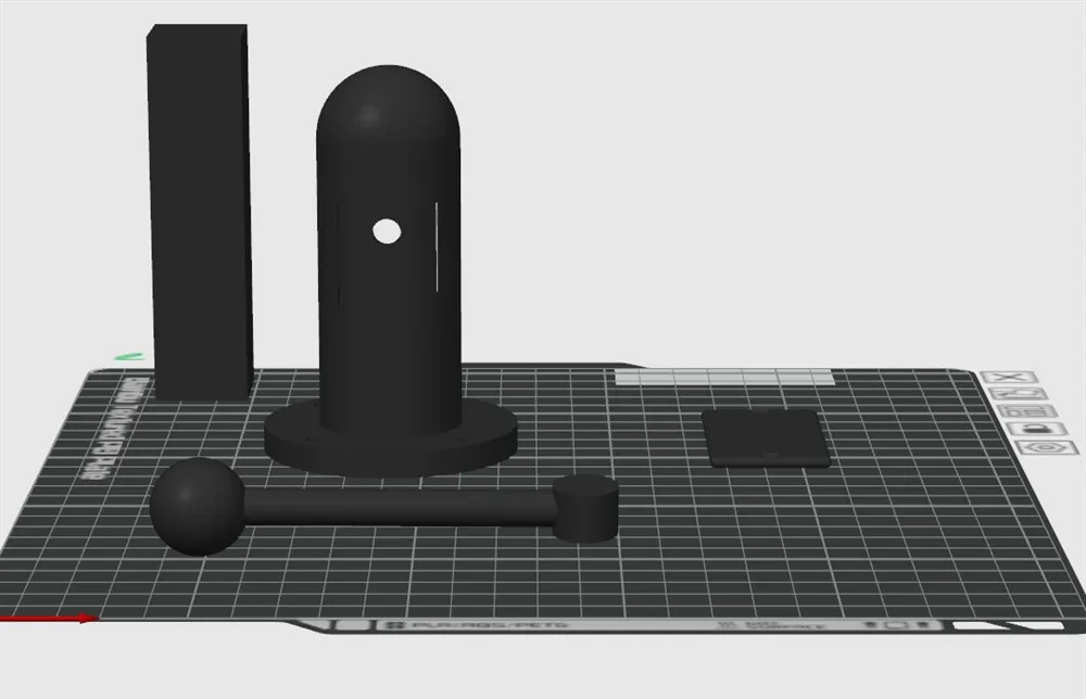
The final set in the slicer. The pillar stands up, the lever lies down, the rear cover sits flat - an arrangement that minimizes supports. The round hole in the side of the pillar is where the potentiometer shaft comes out.
3D printing the lever and pillar for real
3D printing is where a drawing stops being enough; you have to print it and hold it. We printed all three files and mated them with the potentiometer.
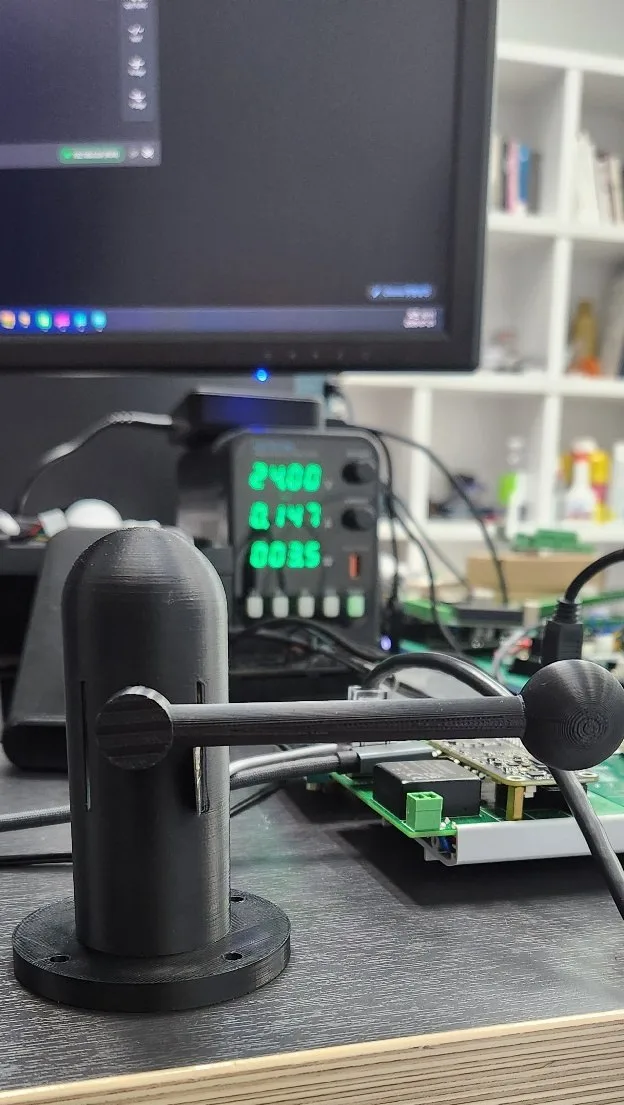
The finished, assembled part. Exactly the shape from the render, and it turns with real weight when you pull it. The 24V power supply in the back was that day’s accomplice.
Open the back of the pillar and you can see the result of the redesign: an open-backed compartment instead of a push-in tunnel, the 45° roof added so it prints without supports, and the wiring dropping out under the base.
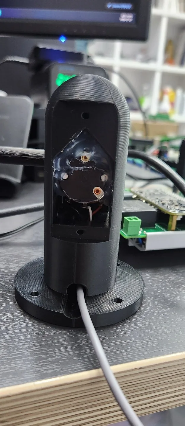
The end of the first design that collapsed under a single photo. The potentiometer with its splayed legs now sits comfortably. The cable runs through the pillar and out beneath the base.
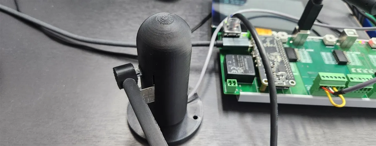
Next to the lever is the brain of the cabinet. Once the wires from the potentiometer reach the controller, the game we built in Part 1 runs off this handle.
Vibration haptics: “make the lever buzz when it opens”
Vibration haptics was the next bit of greed once we had a lever. What if the lever trembled in your hand while you poured? That fine shudder a real tap has when the beer is flowing.
Conveniently, the controller accepts an analog output (DA) expansion board. Raise the voltage in proportion to how far the lever is open and the vibration scales with it - the picture drew itself. The PLC logic took no time at all: “while pouring, output a voltage proportional to lever position.”
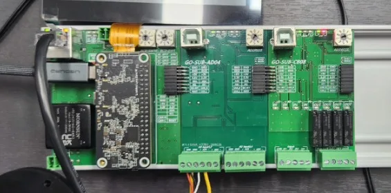
The brain of the cabinet. Expansion boards attach alongside the main controller like cars on a rail, so reading the lever and driving the vibration happen on the same backbone.
The problem was the actuator. Digging through a drawer, we found a vibration actuator harvested from a disassembled Switch Pro Controller - the source of that famously good HD Rumble. This was it, we thought.
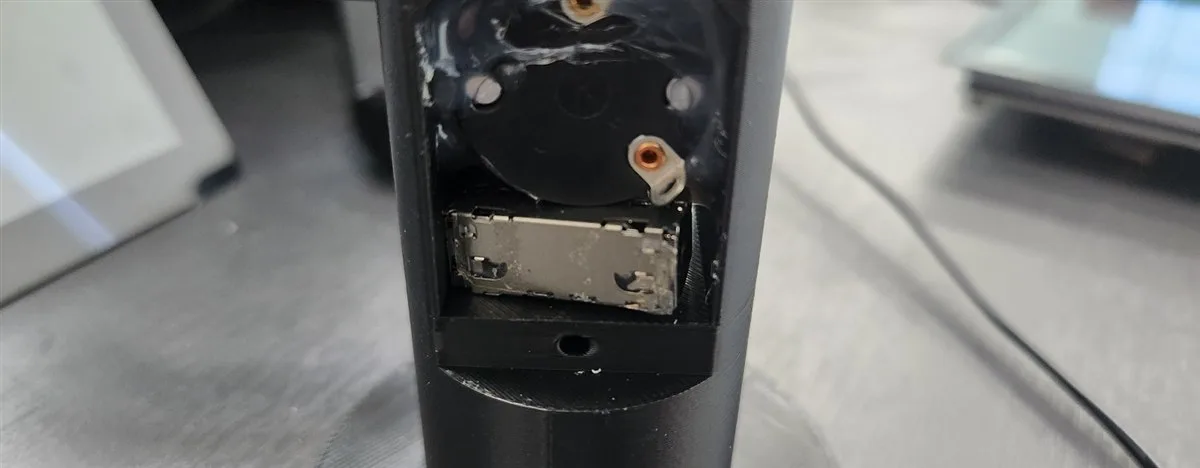
The potentiometer and the actuator pulled from the Pro Controller, seated side by side in the compartment. Up to this point, it looked perfect.
That was the trap.
A chronicle of failure: diagnosing the vibration actuator
The vibration actuator got power. Silence. Raise the voltage. Silence. The multimeter clearly said there was voltage across the actuator, and the actuator did not move.
From there it became a remote investigation. We pinned forced values into PLC memory from the editor’s diagnostic mode and read the multimeter on site (the next desk over), clearing suspects one span at a time.
- Does the value reach the board? → It does (communication acquitted)
- Does an output voltage appear? → It does (board acquitted)
- Is the actuator alive? → Tap the power on and off quickly by hand and it buzzes (actuator acquitted)
Everyone acquitted, and still no vibration. The last experiment cracked the case. Switching slowly does nothing; only switching quickly produces a buzz. This actuator, it turns out, is not the kind that vibrates while you hold a voltage on it.
The culprit: what the actuator actually is
The Pro Controller’s actuator is an LRA (linear resonant actuator). A mass on a spring has to be driven continuously by pulses at its resonant frequency (around 160Hz) to produce vibration, and inside a game controller a dedicated driver chip does that job. Apply DC and the mass slides over once and stops. That was the silence we had been listening to.

An analog output board, meanwhile, exists to produce smooth DC voltage. Its internal filter carefully irons out every ripple and hands you a flat voltage. No matter how clever the software gets about generating pulses, what comes out after the filter is well-pressed DC. The actuator wants pulses; the board gives DC. It failed precisely because both were doing their jobs perfectly.
We rewrote the firmware three times and swept from 20Hz to 320Hz before admitting it. Tapping one wire into the circuit would have solved it. But the rule of this project is “build it from products combined exactly as purchased.” The moment a soldering-iron modification goes in, the “thrown together over a weekend” story falls apart. So we let it go.
The resolution: match the actuator to the board
The answer had been on the other side all along. An ERM vibration motor - a coin-sized body with an eccentric mass spinning inside, the vibration of an old mobile phone. This one shakes in proportion to DC voltage. It is a perfect match for the analog output board. Open the lever and the voltage rises; as the voltage rises it buzzes harder. No circuit modification, no firmware modification.
We gave up the romance of the harvested part and ordered an ERM motor. The Pro Controller actuator went back into the drawer, to be reunited someday with a proper driver.
Recap: 3D printing and vibration actuator lessons
- Real dimensions beat drawings. One photo of the part first, and there would have been no redesign.
- Verify passages you cannot see. Whether it is a wiring hole or a socket, do not believe it is clear - shoot a ray through it and check.
- “Vibration actuator” is not one thing. An LRA needs a dedicated driver; an ERM is the one that suits an analog voltage. The more a part comes out of a parts drawer, the more you should identify it first.
- Remote diagnosis is fun. Pinning forced values and reading a multimeter while eliminating suspects was the most maintenance-technician-like stretch of building a game cabinet.
An analog DC output calls for an ERM vibration motor, not an LRA.
Next up
The lever is in hand, so once the ERM motor arrives it will finally become a trembling lever. Add an enclosure on top of that and the series is complete.
Coming in Part 3: we plugged blackjack into the beer game cabinet, and the cabinet became a platform.
If you missed Part 1: turning a crank into a real lever, rebuilding the Playdate game Root Bear as a PLC and HMI arcade cabinet.
Contact
- Email: [email protected]
- Instagram: https://www.instagram.com/going.sen/
- Website: https://intosen.com/kr/consult/
Comments
Enter a nickname to leave a comment, or sign in with Google or GitHub.