
Hmm.. the first thing to get into on the design side is the ladder. It is the most fundamental piece of a PLC, and the piece whose character is most unlike everything else, so it goes first.
How the Ladder Analysis Works
A ladder is a circuit. It looks like a drawing with symbols lined up on it, but it is a circuit. Does power get from the left rail to the output on the right, or not? In the end, that is all you are looking at.
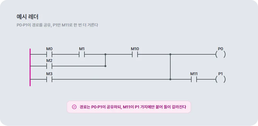
Boiled down, the ladder analysis goes like this.
- Build a path tree from every start node with DFS.
M0-M1-M10-(P0)
M0-M1-M10-M11-(P1)
M2-M10-(P0)
M2-M10-M11-(P1)
M3-(P0)
M3-M11-(P1)- LOOKUP the path list by output node position.
[P0 (1,10)]
M0-M1-M10-(P0)
M2-M10-(P0)
M3-(P0)

[P1 (3,10)]
M0-M1-M10-M11-(P1)
M2-M10-M11-(P1)
M3-M11-(P1)- AND every path in each looked-up list.
[P0 (1,10)]
R1 = M0 & M1 & M10
R2 = M2 & M10
R3 = M3

[P1 (3,10)]
R4 = M0 & M1 & M10 & M11
R5 = M2 & M10 & M11
R6 = M3 & M11
- OR all the AND results for each output, and that is the output.
P0 = R1 | R2 | R3
P1 = R4 | R5 | R6
Look at those steps and it makes sense. Doing the LOOKUP by output node position hands you every path that ends at that position. If ANDing all the nodes on one path comes out true, that path is conducting. And if any one of those paths is true, the circuit is connected. Which means the output is on.
NOT and edges (rising, falling) are a bit different. Edges especially have to hold onto the previous scan’s state, so they are sequential elements and get handled separately.
The Scan Execution Model
Two loops run apart from each other. A deterministic ladder loop and a free-running C# loop. They are separate Tasks, so neither one blocks the other’s timing. But they do interoperate. C# reads the memory values the ladder wrote, and methods (functions) defined in C# can be called from the ladder. They run separately, but they are tied into one body.
Ladder loop
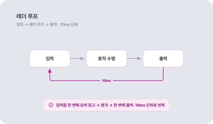
- Input, ladder loop, output. Read all the inputs in one go, run the logic, push all the results out in one go.
- Inputs are pinned at the start of the loop, so nothing changes mid-run. No races, predictable behavior. Concurrency serialized by time.
- Fixed at 10 ms: if each loop rests with a sleep, the period slips (drift) whenever processing runs long. So instead it measures elapsed time, snaps to a 10 ms grid, and catches up by however much it fell behind. The load can wobble and it still holds 10 ms.
C# loop
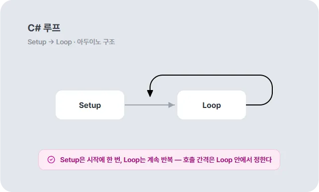
- Same structure as an Arduino. Setup, then Loop.
- Setup: an init routine that runs once at start.
- Loop: called over and over. The interval between calls is set inside Loop itself. Not a fixed period like the ladder. You pick whatever you want.
.NET and the Raspberry Pi
I left the ladder execution model alone and put .NET on top of it. Why .NET, and why the Pi?
.NET ↔ PLC - covering each other’s weak spots
- A PLC is strong on determinism, scanning, and real time. It runs the same way every time, at a set period, in a set order. The cost is that it is closed, hard to extend, and tied to a vendor.
- .NET is strong on ecosystem, extensibility, and tooling. Grabbing something someone else built and bolting it on is easy. The cost is that things like memory cleanup (GC) can cut in mid-run and shake the execution timing, so the common wisdom is that it is weak at hard real time.
- Each one’s weakness gets covered by the other’s strength. .NET’s timing jitter is pinned down at build time (the way a ladder download is) and C# pries open the PLC’s closed nature.
Why a Raspberry Pi
- Hardware extension and customization is easy. GPIO, boards, peripherals: attach and swap them freely.
- It runs Linux, so it is easy to handle. Develop and deploy with familiar environments and tools.
- There is a lot of material out there. When you hit a wall there is something to look up, and plenty of room to try different things.
System Layout
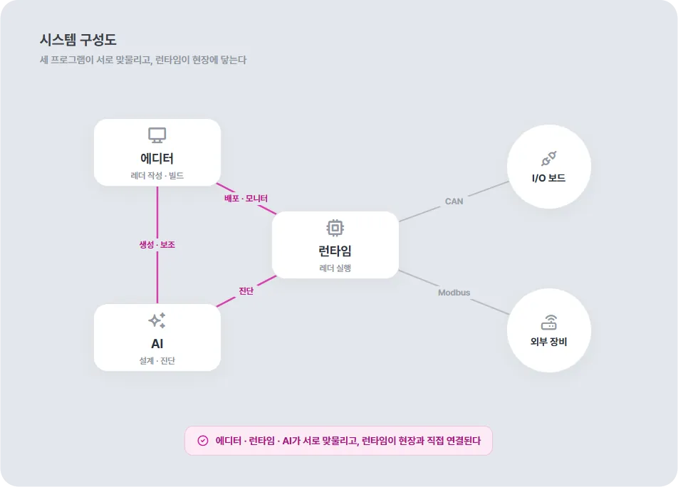
The editor, the AI, and the runtime are the core components of this system. They handle authoring, assistance, and execution respectively, and those three are not a one-way pipeline. They form a ring that passes things back and forth.
- Editor - The workspace where a person writes ladder and C#. It deploys the build output to the runtime and pulls the runtime’s running state back to monitor it. The AI attaches here too, over MCP.
- Runtime - Lives on the target, takes the build output, and runs it through the scan loop. The body that does the PLC’s ‘executing’.
- AI - Attaches to the editor and helps with ladder and code generation, progress reports, diagnosis, even fixes. From design through operation.
- I/O boards - Read and write the sensors and actuators in the field. I/O expansion hooked to the runtime over CAN.
- External devices - Instruments, other controllers, and the like, tied in over Modbus. The runtime exchanges values with them over comms.
Program Structure
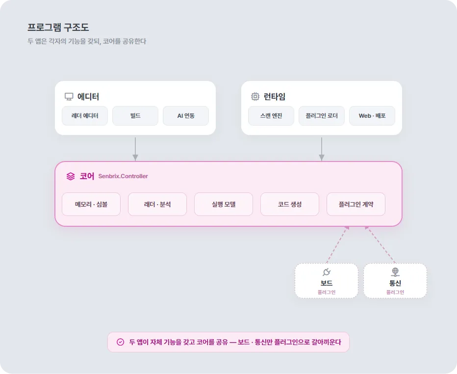
If the system layout was about who is wired to whom, once you get into the code the point is a single one. The editor and the runtime each add their own features on top, but they share one core.
- Shared core (Senbrix.Controller) - Memory and symbols, ladder and analysis, the execution model, code generation, the plugin contracts. All of it lives here. The conduction paths and the scan model I walked through above are part of this core too. Both apps use the same core, so what you write in the editor and what runs in the runtime cannot drift apart. This is the foundation that lets ladder and C# bind together like one program.
- Extensions are plugins - Every site has its own I/O boards and its own comms protocols. Put all of that in the core and you rebuild the core every time a new site comes along. So boards and comms were pulled out into plugins. Match the contract and the runtime plugs it in and loads it, and the core is never touched.
Communication Between Programs
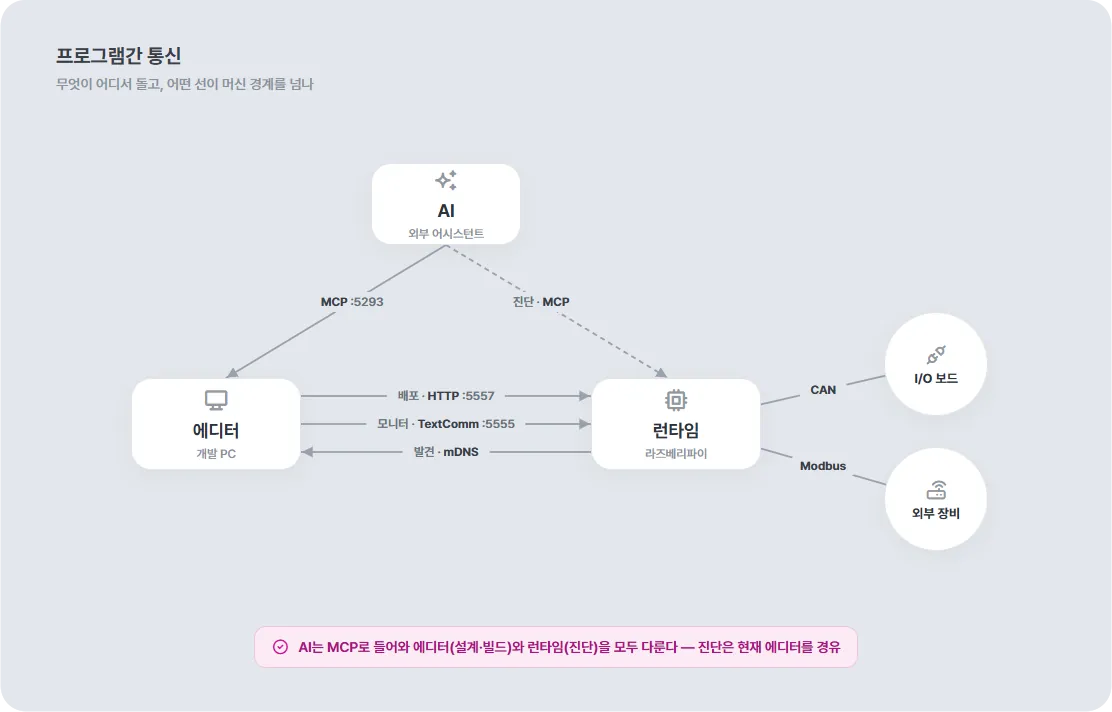
As shown above, the editor, AI, and runtime are the core components, and the system does its work through calls between them. On the same computer it is just a call. Protocols and ports only get attached on lines that cross a machine boundary.
- AI ↔ Editor (MCP ) - Ladder and code generation, builds, progress reports. Helps with design and authoring.
- AI ↔ Runtime - Reads, controls, and diagnoses the running state against the ladder graph. But letting the AI touch the runtime directly has security issues, so this is left as something to sort out later.
- Editor ↔ Runtime - The comms format is split by function and purpose.
- Deploy (HTTP ): uploads the build output (ladder.json + DLL).
- Monitor (TextComm ): receives snapshots of runtime values.
- Discovery (mDNS): advertises and finds device names and ports.
- Runtime ↔ Field - I/O board inputs and outputs over CAN, external device values over Modbus.
Next - C# and Ladder
This part covered the design. From the next part on, it is about how it was actually built and what the built thing looks like. The first implementation topic is C# and ladder: how the two get bound inside one program, and how they call each other.
Comments
Enter a nickname to leave a comment, or sign in with Google or GitHub.