
From Part 3 on, this series gets into the actual implementation. This part covers how the C# side and the PLC side were built, and how you use them.
To keep the explanation grounded I put together a small example. Count products as they pass a sensor, and when the count hits a target, report it to a server. Counting is what ladder has always done. Reporting to a server is not something a PLC ever did on its own. You’d normally stand a PC next to it or bolt on a data collector and hand the job over. That’s the grunt work I complained about in Part 1. Here, the ladder calls a C# function and handles the report itself.
I’ll walk through how this example is set up and built, and along the way look at each piece of the program, how it’s used, and why it was made the way it was.
Project
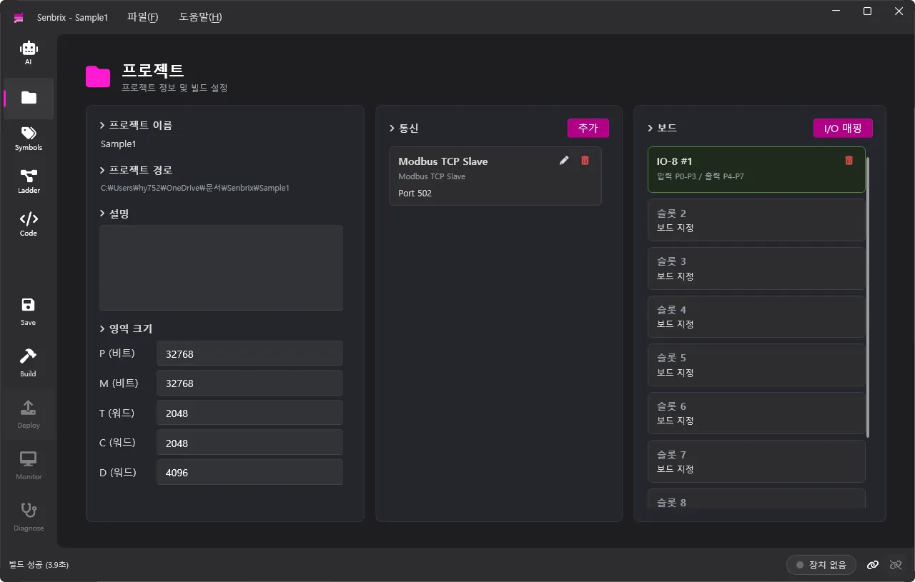
The project page is where you define what this PLC is. Memory area sizes, which boards go in which slots, and communication links all get set here.
Memory area sizes
The area size section sets how big each memory area is. Memory is split into five areas.
| Area | Unit | Default | Purpose |
|---|---|---|---|
| P | bit | 32768 | Physical I/O. Real inputs and outputs like sensors and motors land here |
| M | bit | 32768 | Internal flags used by the program |
| T | word | 2048 | Storage for ladder timer instructions |
| C | word | 2048 | Storage for ladder counter instructions |
| D | word | 4096 | Data registers that hold numeric values |
Timers can only live in T, and counters only in C.
Boards
The board section picks which boards this project uses. There are up to nine slots. Click a slot, choose a board, and it’s plugged in. A plugged-in board gets its inputs and outputs mapped into the P area and its AD/DA channels into the D area automatically. If you want something different, change it in the I/O mapping.
The list of boards you can pick from is not hard-coded. It’s built by scanning the DLLs in the Modules folder, which makes it easy to extend. You can write one of these DLLs yourself as long as it follows the interface contract.
Communication
The communication section defines the links this PLC will use to talk to outside equipment. Hit Add, pick a protocol, and fill in the connection settings. Four come built in: Modbus RTU and TCP, each as master and slave.
The protocol list works the same way as the board list. Scan the Modules folder for DLLs, and write your own against the interface if you need to.
Add a slave and the PLC memory gets exposed to the outside as a standard Modbus table. The D area is split at a boundary address (100 by default): everything below it is read-only, everything from it up is writable. This is where a supervisory system or an HMI plugs in.
The example
This example keeps the default area sizes as they are. For the board, I put an IO-8 in slot 1 to take the product sensor. Inputs land on P0 to P3, outputs on P4 to P7, and the sensor comes in on P0. For communication I added a Modbus TCP Slave on port 502. From outside you can read 생산수량 (production count, D0) and write a new 목표수량 (target count, D100). Putting the target symbol at D100 was deliberate. That’s the boundary.
Symbols
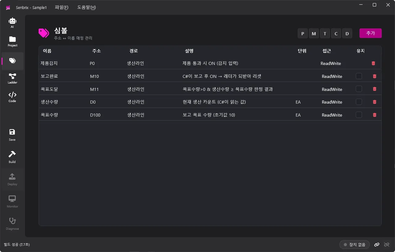
A symbol is a name attached to a memory address. Write everything in raw addresses and you won’t be able to read it a month later. So instead of P0 you name it 제품감지 (product sensor), something that says what it is, and use that same name in both ladder and C#. The symbol page is where these get registered and managed as a table.
What a symbol is made of
| Column | What it holds |
|---|---|
| Name | The identifier used in code. Case-sensitive, and Korean is allowed |
| Address | The memory address. The suffix decides the type |
| Path | Equipment hierarchy. Groups signals into a tree by which device they belong to |
| Access | Read-only or read-write |
| Description, unit | A note on what the signal means and its unit |
| Retain | Whether the value survives a restart |
Memory resets to 0 on restart. A symbol with Retain on keeps its value across a power cycle. Retain only applies to M, C and D. P is physical I/O, so it gets read fresh from the hardware after a restart and there’s nothing worth saving. At build time the addresses of all retained symbols are gathered into ranges, signed, and shipped to the runtime. The runtime saves only those ranges to a file and restores them on restart. It restores only if the project and the signature match.
Columns like address, path and description are not there just for humans. When AI writes, analyzes or diagnoses ladder and code, it works from this symbol information.
Address types
You may have noticed the table has no column for data type. The address decides the type. More precisely, the suffix hanging off the address decides it. Memory is a byte buffer in the end, and the D area views it in words. The suffix is how you read a given spot.
| Suffix | Meaning | Width | C# type | Ladder expression | C# expression |
|---|---|---|---|---|---|
| (none) | Unsigned 16-bit, same as .W | 1 word | int | D0 | D[0].W |
.W | Unsigned 16-bit | 1 word | int | D0.W | D[0].W |
.I | Signed 16-bit | 1 word | int | D0.I | D[0].I |
.DW | Unsigned 32-bit | 2 words | uint | D0.DW | D[0].DW |
.DI | Signed 32-bit | 2 words | int | D0.DI | D[0].DI |
.R | float | 2 words | float | D0.R | D[0].R |
.S | String (UTF-8, up to 256 bytes) | variable | string | D0.S | D[0].S |
.L | Low byte | 1 byte | int | D0.L | D[0].L |
.H | High byte | 1 byte | int | D0.H | D[0].H |
.0 to .15 | Individual bit within the word | 1 bit | bool | D0.3 | D[0].Bit[3] |
The same D0 becomes an integer, a float or a string depending on the suffix. One location, viewed through several types at once. The catch is that .DW, .DI and .R take two words, so D0.R occupies both D0 and D1.
The ladder and C# expressions differ because of what C# syntax allows. D0.3 is not a valid expression in C#, so on that side the same spot is reached through an indexer and a property: D[0].Bit[3].
P and M are bits, so they take no suffix. If you want to see a bit area as words, use WP and WM. These are not separate memory. They’re the same buffer as P and M, viewed a word at a time. Write to WP0 and P0 through P15 change.
The example
This example has five symbols. 제품감지 (product sensor) on P0, 생산수량 (production count) on D0, 목표수량 (target count) on D100, 보고완료 (report done) on M10, and 목표도달 (target reached) on M11. Physical input goes in P, numbers in D, internal state in M. I never picked a type for any of them.
Ladder
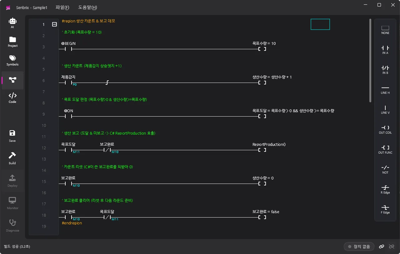
Ladder is the language that draws machine control out of contacts and coils. The ladder page is where you write the program in it. Below I go through how you write it, the functions, and how special relays are used, in that order.
Writing ladder
You write ladder by dropping elements into cells on a grid, one per cell. Pick them from the palette on the right or hit a shortcut key. These are the elements you can place.
| Element | Shortcut | Kind | Description |
|---|---|---|---|
| NONE | Space | Delete | Empties the cell. For removing what you placed |
| IN A | F3 | Input, A contact | Normally open. Passes when the value is on |
| IN B | F4 | Input, B contact | Normally closed. Inverts the value, so it passes when the value is off |
| NOT | F9 | Input, invert | Inverts the result up to that point |
| R Edge | F11 | Input, edge | Rising edge. Passes for one cycle only, the moment it goes from off to on |
| F Edge | F12 | Input, edge | Falling edge. Passes for one cycle only, the moment it goes from on to off |
| LINE H | F5 | Wire | Horizontal wire. Carries left to right |
| LINE V | F6 | Wire | Vertical wire. Ties the rows above and below in parallel |
| OUT COIL | F7 | Output | Writes the rung result into a bit |
| OUT FUNC | F8 | Output | Calls a function or a C# method when the rung passes |
Each cell has a position, a kind, and a code (an address or an expression). Column 0 on the far left is the power rail. Chain contacts left to right and you get a series AND. Tie rows together with a vertical line and you get a parallel OR. If there’s a path from the rail on the left to the output on the right, the rung passes.
There are two kinds of output. A coil writes the result into a bit. A function runs code. Whatever you write in the function cell runs when the rung passes, whether it’s an assignment like 생산수량 = 생산수량 + 1 or a function call.
Ladder functions
Ladder functions are the built-in instructions you put in a function cell. These are the instructions any PLC ships with, timers and counters and the like. Right now there are sixteen of them in five groups.
| Group | Instruction | Description |
|---|---|---|
| Timer | TON | ON delay. Counts while the condition is on and turns the relay on when it reaches the preset. 10 ms units |
TAON | ON delay. 100 ms units | |
TOFF | OFF delay. Turns the relay off once the preset time has passed after the condition goes off. 10 ms units | |
TAOFF | OFF delay. 100 ms units | |
TMON | Monostable. Even a momentary condition turns the relay on for the preset time. 10 ms units | |
TAMON | Monostable. 100 ms units | |
| Counter | CTU | Increments on each rising edge. Turns the relay on at the preset |
CTD | Decrements on each rising edge. Turns the relay on at zero | |
CTR | Resets the counter when the condition is on | |
| Output | SETOUT | Sets the relay when the condition is on (latch) |
RSTOUT | Resets the relay when the condition is on | |
| Master control | MCS | Start of a section. Numbered 0 to 15 |
MCSCLR | End of the section with the same number. Paired with MCS | |
| Data | WXCHG | Swaps two word values |
DIST | Splits 16 bits into 4-bit nibbles and stores them | |
UNIT | Gathers the low nibbles into one word |
Take counting. You could write it as a plain assignment, 생산수량 = 생산수량 + 1. Or you give CTU a counter address and a preset, and it counts every time the input rises and turns the relay on when the preset is reached.
These instructions check their arguments. A timer relay has to be in the T area, a counter in C, a preset between 1 and 65535. Each slot takes only what it’s supposed to. Get it wrong and the build catches it.
These sixteen are the bare foundation of ladder. I didn’t add more, and the reason is C#. A typical PLC also ships arithmetic, comparison, conversion and communication as part of its instruction set. In Senbrix, C# takes that seat. Math, string parsing, date arithmetic: .NET already has all of it, and there’s no reason to rebuild it as ladder instructions. Ladder functions cover only the floor that machine control needs.
Special relays
In a contact cell you can also put a special relay, which starts with @, instead of an address. These are not memory addresses. The runtime updates them.
| Token | Meaning |
|---|---|
@ON / @OFF | Always ON / always OFF |
@BEGIN | ON only during the first cycle |
@10R to @1000R | Periodic pulse. ON for one cycle every N ms (8 periods: 10, 20, 50, 100, 200, 250, 500, 1000 ms) |
@F10R to @F1000R | Flicker. Toggles ON and OFF every N ms (same 8 periods as above) |
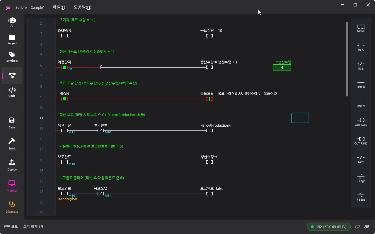
The example
  @BEGIN                                     목표수량 = 10
──┤ ├───────────────────────────────────────────[ ]
The first rung is initialization. On the @BEGIN contact, 목표수량 is set to 10. @BEGIN is on only during the first cycle, so the target becomes 10 exactly once, at startup.
  제품감지                            생산수량 = 생산수량 + 1
──┤ ├────┤↑├────────────────────────────────────[ ]
The second rung counts. A rising edge sits after the 제품감지 contact, and 생산수량 goes up by one. The edge holds last cycle’s state and compares it with this one, passing for a single cycle only at the moment it flips from off to on. Without it, the count would keep climbing every 10 ms for as long as the sensor is held.
  @ON                  목표도달 = 목표수량 > 0 && 생산수량 >= 목표수량
──┤ ├───────────────────────────────────────────[ ]
The third rung is the check. The always-on @ON contact assigns 목표도달. Every cycle it recomputes whether a target is set (> 0) and whether the count has reached it, and refreshes the 목표도달 bit.
  목표도달     보고완료                     ReportProduction()
──┤ ├────────┤/├────────────────────────────────[ ]
The fourth rung calls C#. The 목표도달 contact and the B contact of 보고완료 are wired in series. It passes only when the target is reached and nothing has been reported yet. When it passes, it calls ReportProduction().
  보고완료                                    생산수량 = 0
──┤ ├───────────────────────────────────────────[ ]
The fifth rung resets. It picks up the 보고완료 that C# wrote and puts 생산수량 back to 0.
  보고완료     목표도달                       보고완료 = false
──┤ ├────────┤/├────────────────────────────────[ ]
The sixth rung clears. After the count resets and 목표도달 drops, it drops 보고완료 and gets ready for the next round. Ladder evaluates rungs top to bottom, so this order is the order things happen.
Code
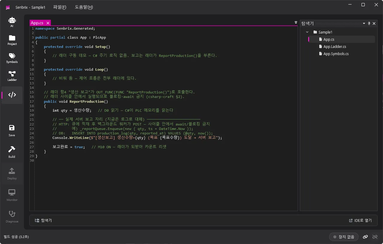
The code page is where you write your own C#. The editor only goes as far as syntax highlighting, so for any real coding session where you want autocomplete and the rest, ‘Open in IDE’ and working in an external IDE is a lot more comfortable. The explorer shows three files: App.cs, App.Ladder.cs, App.Symbols.cs. App.cs is the one I write by hand. App.Ladder.cs is generated from the ladder at build time, and App.Symbols.cs from the symbols. The ladder drawn earlier and the symbols registered earlier turn into C# here and join up. You can open and edit the two generated files, but they’re regenerated on every build, so there’s no point. The source of truth is the ladder and symbol pages.
Ladder + C# = App
App is a single class where ladder and C# merge, and it’s the actual PLC program. The three files on the code page are partials of App, the body of a program that inherits PlcApp. So when you build, the ladder logic, the symbol properties and my hand-written C# all become members of the same App, and the output is a single App.dll.
Stripped to the minimum, the PlcApp that App inherits looks like this.
public abstract class PlcApp : CsApp
{
    // PLC memory, shared by ladder and C#
    public IBitMemory P { get; }
    public IBitMemory M { get; }
    public IWordMemory T { get; }
    public IWordMemory C { get; }
    public IWordMemory D { get; }

    // Ladder entry point, called by the 10 ms cycle. Overridden in App.Ladder.cs
    public virtual void LadderLoop() { }

    // User C# entry points, run on a separate Task. Overridden in App.cs
    protected virtual void Setup() { }
    protected virtual void Loop() { }

    // Ladder function instructions
    protected void TON(int idx, int val, bool condition) { /* … */ }
    protected void CTU(int idx, int preset, bool condition) { /* … */ }
    // …

    // Boards and communication
    public List<IBoard> Boards { get; }
    public List<ICommProtocol> Communications { get; }
}
This PlcApp does not live in the project. It lives in the Senbrix.Controller core. The editor builds against this core and the runtime on the Raspberry Pi uses the same core, so what you write in the editor and what runs on the floor don’t drift apart.
The build itself is nothing special. Write the ladder and symbols to disk as .cs files and dotnet build the project. There’s no embedded compiler, just an ordinary C# build. Which means errors come out as ordinary C# compile errors. The one addition is that every line of generated ladder code carries its original ladder coordinates as a comment, so when the compiler points at some line of App.Ladder.cs, that maps back to a row and column in the ladder and is shown that way.
Let’s look at what goes into each of the three files.
User C# (App.cs)
App.cs is the one of the three that I write by hand. The C# in here lives two lives. One is functions the ladder calls. The other is Arduino-style Setup and Loop. These override the entry points from the sketch above. Setup runs once at start, Loop keeps going, and it runs on a separate Task so it doesn’t collide with the ladder cycle.
Symbol access (App.Symbols.cs)
App.Symbols.cs gets a property for every name registered on the symbol page.
public int 생산수량 { get => D[0].W; set => D[0].W = value; }What follows the name is the address, verbatim. Ladder and code both go through this property, touching the same memory by the same name. This is why in C# you can read and write 생산수량 as if it were a plain variable.
Calling C# (App.Ladder.cs)
App.Ladder.cs is where the ladder lands as C# code. The fourth rung of the example comes out roughly like this.
_result_ = 목표도달 & !보고완료;
if (_result_)
{
    ReportProduction();
}
Contacts become a condition, and when it passes the function runs. The 목표도달 and 보고완료 in the condition are the symbol properties we just saw, and the ReportProduction() call is inside the same class, so it’s a plain method call. No reflection, no events.
Here’s the thing though. The output of that fourth rung is also a function cell. The same cell where the timers and counters from the ladder function set go. So why does ReportProduction() become a C# call rather than a ladder instruction? The ladder looks the function name up in the instruction set first. If it’s a name it knows, like TON or CTU, it plants that built-in instruction. If not, it drops the text in as a C# expression, as is. ReportProduction is not in the instruction set, so it goes in as a C# function call. Same cell: a known name becomes a ladder instruction, an unknown name becomes the C# I wrote.
Extensibility
Ladder normally lives inside the instructions the vendor gave you. Need something outside that list and you’re stuck. So you hand it off. Senbrix ladder, when it hits the wall, calls C#. And C# gets all of .NET. Call an API over HTTP, insert into a DB, read a file, run a heavy calculation. What ladder can do is no longer tied to the ladder instruction set. The ladder function set is the floor. C# opens the ceiling above it.
You don’t even have to go far. A library of control, signal and metering algorithms comes built in, so PID, filters, totalizers and the like are called, not written. If that’s not enough, add a NuGet package. One line in the build settings file and it survives the next build.
The roles stay separate. When to act, whether it’s safe, what state we’re in: ladder decides. What to compute and where to send it: C#. The function call is the bridge between the two.
An open ceiling does not mean anything goes. A function the ladder calls runs inside the ladder cycle. If it takes a long time, the cycle stalls right there. The 10 ms slips. So no await and no blocking. Even the send to the server is not fired directly; it goes into a queue and gets handled in the background. The function reads a value, sets a flag, and gets out. The ceiling is open, with one rule attached: don’t block the cycle.
The example
The user C# in this example is a single function, the ReportProduction() that the fourth rung calls.
public void ReportProduction()
{
    int qty = 생산수량;              // read 생산수량 (D0)
    // Server report goes here: HTTP POST or DB INSERT
    Console.WriteLine($"[생산보고] 생산수량={qty} 목표 도달");
    보고완료 = true;                 // tell the ladder the report is done
}
Read the count, send it to the server, mark it done. The server send is just a log line for now, but HTTP POST or DB INSERT, write it in C# and it works. The fifth rung of the ladder picks up the 보고완료 that C# wrote and resets, and that works because both sides touch the same memory. All the control flow is in the ladder, so Setup and Loop are left empty.
For a ladder engineer, server reporting and DB loading were always someone else’s territory. That’s why the PC got stood up next to the PLC. Here, the ladder counts the machine, and only when it needs to reach outside does it call this function. It never leaves ladder, and the job the programmer used to do happens inside the same program.
Wrapping up
The sensor on the floor comes in on P0 and the ladder counts. Hit the target and the ladder calls C#. C# reads the count and reports it, then writes 보고완료, and the ladder picks that up and resets. Meanwhile the supervisory system reads 생산수량 over Modbus and, when it needs to, writes a new 목표수량.
The job from Part 1, standing up a second PC next to the PLC to run a collection program, is handled here by a few rungs of ladder and one C# function. The person who wrote the ladder sends values to a server without ever leaving ladder.
Next up - Running on the Raspberry Pi
That’s the writing part. Actually running this on a Raspberry Pi is Part 4.
Comments
Enter a nickname to leave a comment, or sign in with Google or GitHub.