
Hand-soldering a PCB goes one reel at a time. You open the 1kΩ reel, fill every 1kΩ position, then move on to the next reel. The parts list gives those positions as R6 R8-9 R22-25 R31 R38 R42-45 R51 R58. The slow part isn’t the soldering. It’s finding where those designators are on the board.
Fifteen 0603 chip resistors are scattered across the bottom side, and the silkscreen is tiny or already hidden under parts you placed earlier. A double-sided board is worse: flip it over and left and right swap, so you have to mirror the artwork screen in your head. So we built a soldering helper that takes a board file and highlights every part of the same value on a drawing of the board.
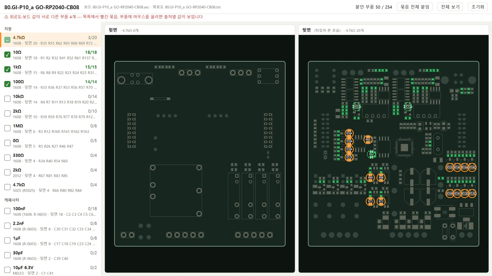
What the screen shows
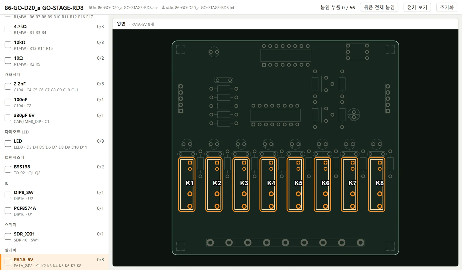
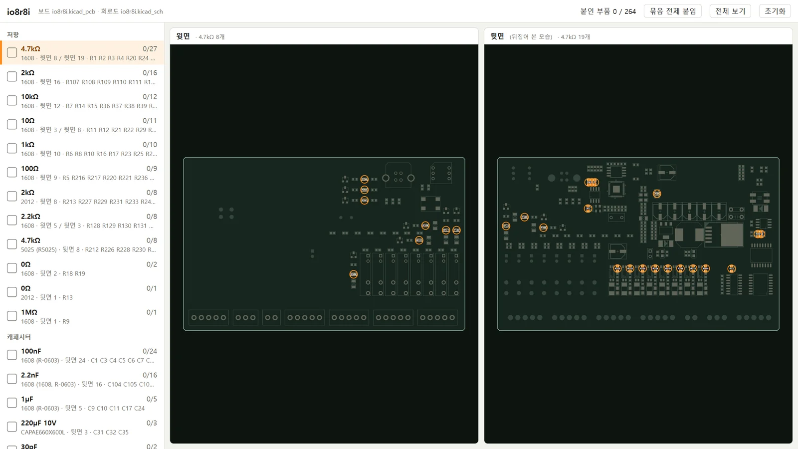
On the left is the list of same-value groups: resistors, capacitors, diodes, transistors, ICs, then connectors, so the order follows the usual low-profile-first assembly sequence. Pick a group and its parts light up on the board as orange circles with their designators. Even 0603 chips stand out in the full-board view, and scrolling to zoom makes the designators readable.
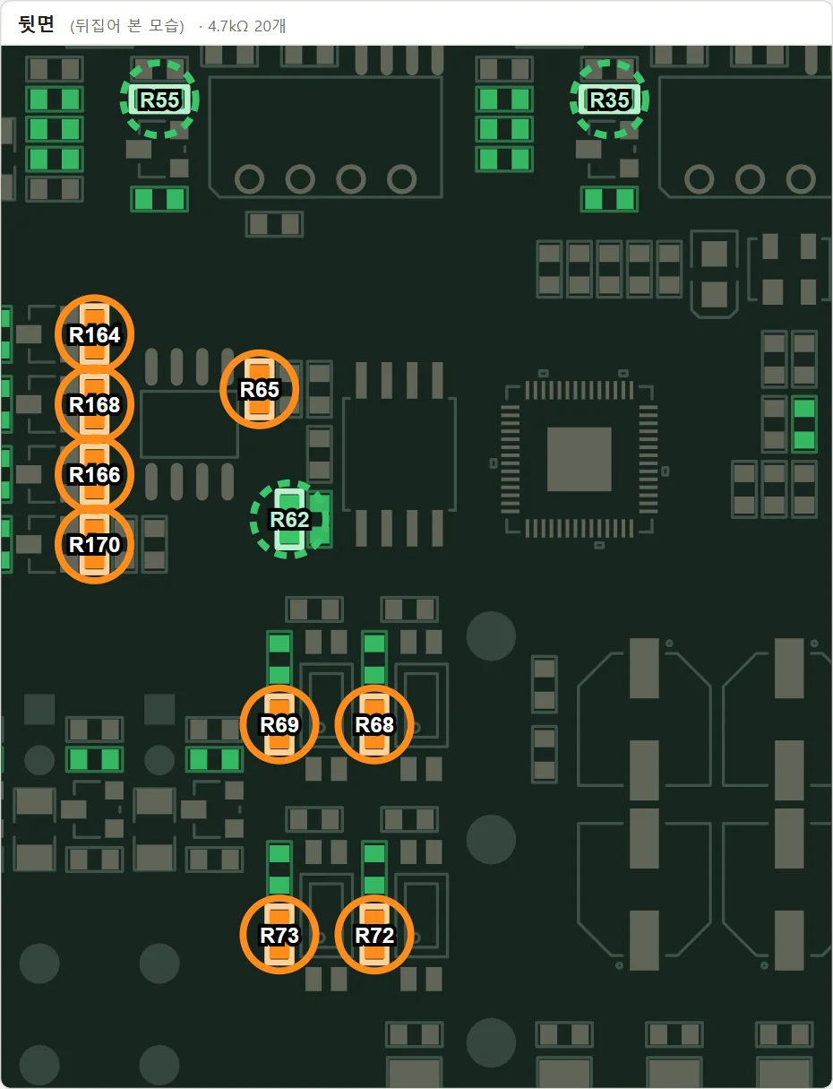
For a double-sided board, the top side and the flipped bottom side sit next to each other. The bottom view matches the board turned over left to right, so you can compare the screen and the board directly. Large parts get an outline around the part instead of a circle.
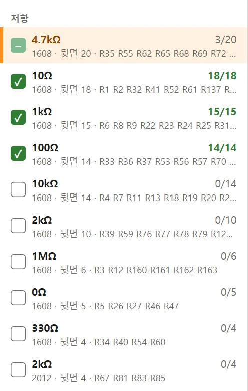
Progress by group
Mark a soldered part with a click or the space bar, and when a group is finished, one checkbox marks the whole group. Soldered parts stay green while you look at other groups, so the progress of the whole board is visible at a glance. Progress is saved in the browser, so you can split the work across days.
Values come from three places
A part’s value can live in the board file’s attributes, in the schematic’s attributes, or in free text written next to the symbol on the schematic. In all 10 PADS schematics we checked, values such as LED colours (RED, GREEN), diode part numbers (1N4148), transistors (BSS138) and crystal frequencies (12MHz) existed only as free text.
That text was often closer to the part actually fitted than the attributes were. Some examples checked against the parts list:
| Part | File attribute | Schematic text | Parts list |
|---|---|---|---|
| Q13 | Part Number BSS123LT1 | BSS138 | BSS138 |
| IC5 | Part type MAX485 | MAX13487E | MAX13487EESA |
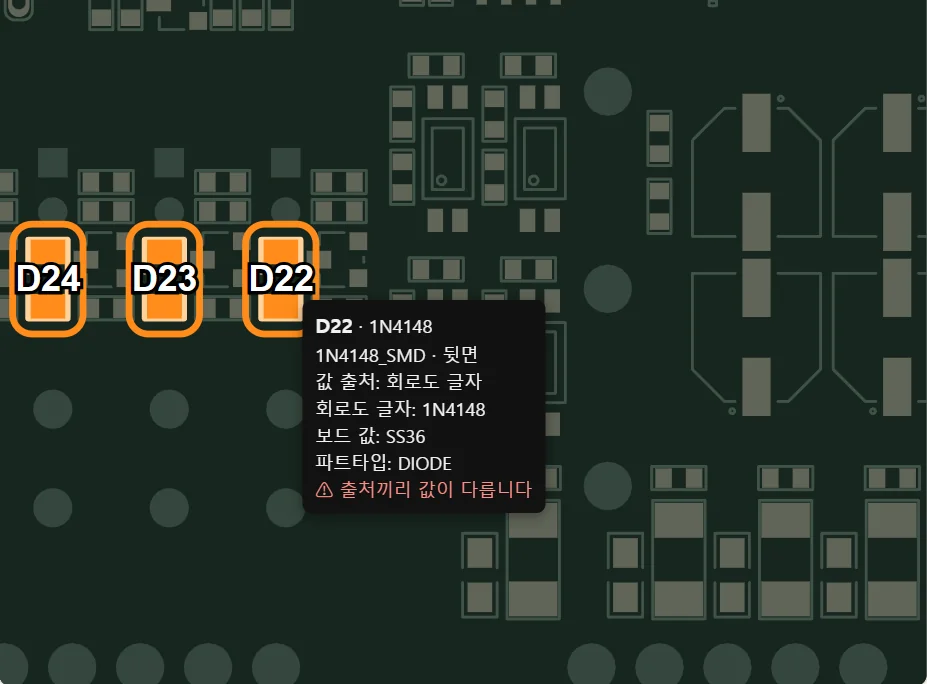
| D22 | Board value SS36 | 1N4148 | LL4148 |
So the helper picks the schematic value first, then the schematic text, the board value, the part number and finally the part type, and marks a part with ⚠ when its sources disagree. Notation differences (102 and 1K, 104 and 0.1uF) are normalised to the same value, and footprints that differ only by name but share a chip size (R-0603 and 1608) go on the same reel.
Matching schematic text to parts
Free text doesn’t say which part it belongs to, so it has to be paired by position. Pairing by distance to each part’s origin sent both labels between two relays to the same relay. The helper now measures the gap between the symbol’s body rectangle and the text rectangle, filters candidates by what the text looks like (a diode part number only goes to a diode), and commits the closest pairs first so that each label goes to exactly one part.
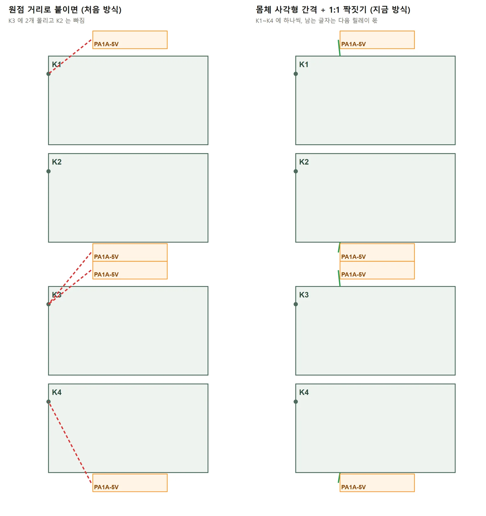
With this, all 38 text labels on the CB08 board landed on the part the parts list says they belong to, and on two relay boards every relay received exactly one label.
Checking positions
A wrong drawing means soldering in the wrong place, so positions were checked against values computed by other programs.
- 12 PADS boards: 4,466 pins compared with the pin coordinates PADS stores in the routing data, zero error
- 12 KiCad boards: every pad matches the IPC-D-356 coordinates exported by
kicad-cli - Schematic symbol rotation and mirroring: about 4,000 pins across 10 PADS schematics all land on wire end points
How misreading PADS coordinate units once made a board come out 1.5× too large is covered in PCB design automation verification: the 1.5× board that passed every gate.
Summary
- Tested on 12 PADS boards and 12 KiCad boards, all of which produced a page, with 89 automated tests passing
- Cross-checking against the parts list also surfaced stale values in the files and parts missing from the list
- The test boards had no KiCad schematic symbol that was both mirrored and rotated by 90°, so for that case the helper follows the order used in the KiCad source
Soldering time is set less by placing parts than by finding where they go. Showing the positions and values already stored in the board file is enough to cut that time.
Contact
- Email: [email protected]
- Instagram: https://www.instagram.com/going.sen/
- Website: https://intosen.com/kr/consult/
Comments
Enter a nickname to leave a comment, or sign in with Google or GitHub.