
Placement had been satisfying. The channel pitch was exactly uniform and the components lined up as if measured. Then we ran the router, looked at the render, and knew it was not right.
A trace that could go straight left instead climbs at a right angle and comes back down. Traces burrow into the narrow gaps between component pads. They climb and drop in short steps, like a staircase. Some traces end touching nothing at all, hanging in mid-air.
The eight routing rules we have to keep
The routing rules accumulated one at a time as we worked. In order, they are these.
| # | Rule |
|---|---|
| 1 | No right-angle (90°) bends — go at 45° |
| 2 | Uniform trace width per net class — signal 0.25 |
| 3 | No traces passing between component pads or vias |
| 4 | Minimize bends — stay as straight as possible |
| 5 | Connect everything that can go in one shot first, then the rest |
| 6 | GND: drop SMD pads through vias, leave DIP to the pour |
| 7 | Pour connections use thermal relief spokes — not a solid tie |
| 8 | No traces ending in mid-air (antennas) |
DRC catches none of these. As long as clearance is met, running between pads passes, a staircase passes, and an antenna passes because “the connection is fine.” So every rule needed a checker of its own.
Antennas — what DRC can never catch
An antenna trace is one whose end touches no pad, no via, and no other trace. The other end is on the net, so the connection is valid, and DRC says nothing.
Electrically it is an antenna. It picks up noise and radiates it. And it simply looks sloppy.
The check is easy. Count the degree of every trace endpoint and find the points with degree 1 that are not at a pad or via coordinate. Deleting one turns its neighbor into a new antenna, so repeat until nothing changes.
Pre-routing by hand, the rest to the router — three failures
Manual pre-routing came out of blaming the staircases and the detours on the router: we would lay the important traces at 45° ourselves and hand the remainder over. We tried three variations.
| Approach | Right-angle bends | Unrouted |
|---|---|---|
| Everything to the router (empty board) | 10 | 9 |
| 45° pre-routing + channel 1 copied + router | 80 | 48 |
| Channel nets routed by hand + router | 65 | 54 |
All three came out worse. In hindsight it is obvious. Traces we lay down are obstacles the router cannot touch. More obstacles means it has to force its way through whatever space is left, which adds right angles, and where it cannot get through at all the net stays unrouted.
A textbook case of local optimization wrecking the whole. We kept this table on file so that the next time the same temptation appears, we do not try it again.
What actually causes staircases — per-layer routing direction
A staircase post-processing tool came first, straightening staircase routing by re-laying whole runs along a minimal 45° path. It helped, but it was not a fix — the router kept producing staircases, so we kept chasing them.
The cause was the absence of a preferred direction per layer.
This is as basic as PCB routing gets: each layer gets a preferred direction.
| Layer | Direction |
|---|---|
| Component side | Mostly X (horizontal) |
| Solder side | Mostly Y (vertical) |
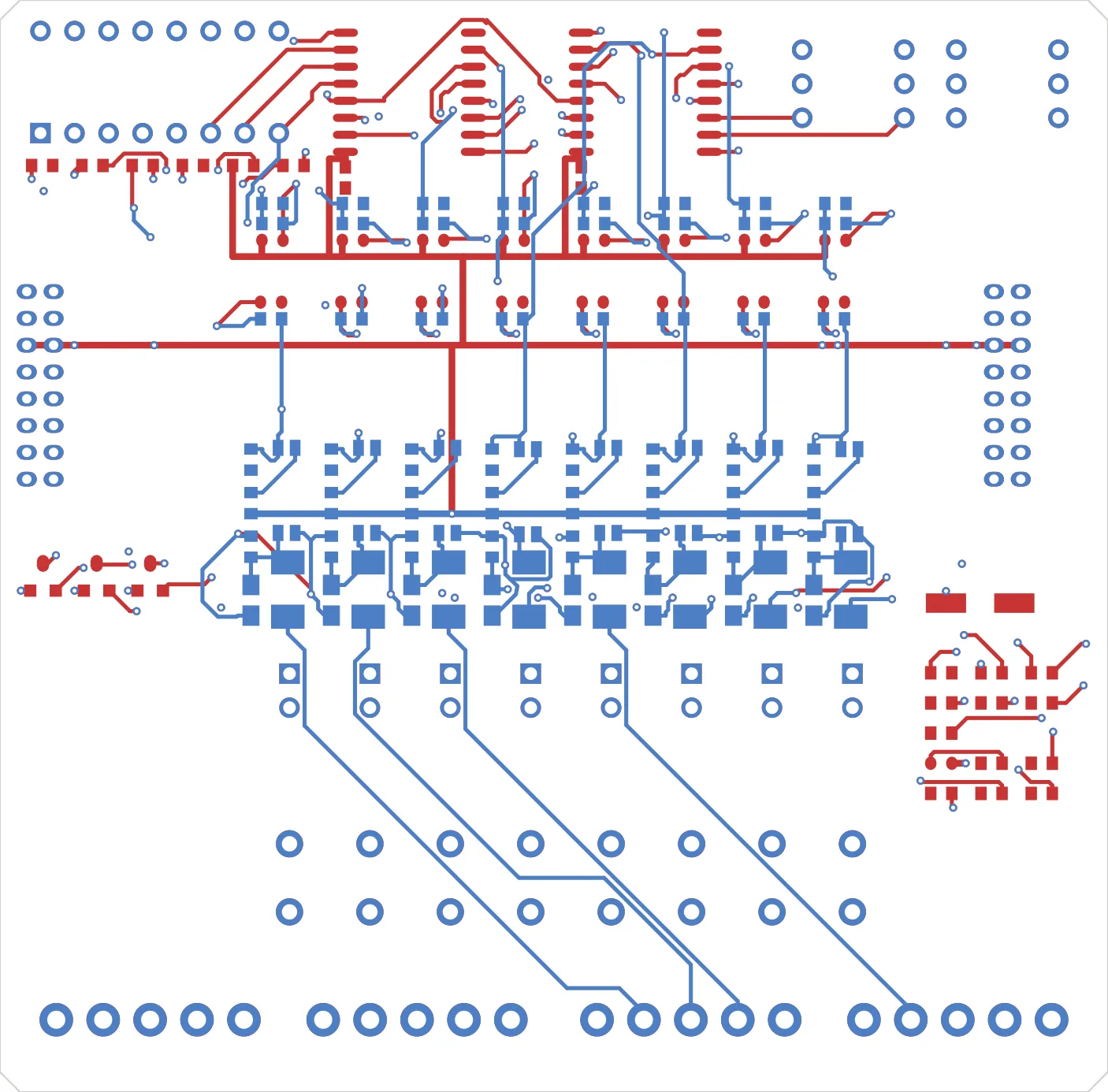
The two outer layers only, pulled from the finished board. At the time of Part 4 these two were all we had, and all 16 channels had to fit on them. Wherever a horizontal trunk and a vertical trunk meet on the same layer, detours and staircases appear. Put this next to the picture in Part 6, after the two inner layers were added, and the difference is unmistakable.
Without directions the router tries to go diagonally on one layer, gets blocked, and alternates short diagonals with short straights. That is a staircase. Give it directions and horizontal runs go on the top layer, vertical runs go on the bottom, and direction changes happen through vias.
When KiCad exports Specctra DSN it writes only an index in the layer properties, with no direction. So we inject the direction after the export.
(layer top_cu
  (type signal)
  (property
    (direction horizontal)   ← insert this line
    (index 0)
The Freerouting CLI has no option for angle or direction at all. Writing it into the file was the only way.
Right angles and trace widths kept coming undone
The fixes we had already applied did not stay applied. Even after all that, things we had fixed came back a few rounds later. Right angles were down to 10, and the next measurement said 101. Trace widths were unified, and then they were not.
We read this as an ordering problem in the post-processing and kept shuffling the order. Ordering really was part of it — a step that moves vias or changes widths after the 45° cleanup brings right angles back. So we made the 45° cleanup run once more at the very end.
None of this routing quality is caught by DRC — every rule needs a checker of its own, and staircases are fixed by giving each layer a preferred direction.
But that did not explain everything. The real cause was far stranger, and it is Part 5. Our verification tool was rewriting the thing it was verifying.
Part 5: The measurement was changing the thing being measured — and the answer key we found in our own shipping boards
Earlier in this series: Part 1, Part 2 on the 1.5× board, and Part 3 on the library and the 3D model rabbit hole.
Contact
- Email: [email protected]
- Instagram: https://www.instagram.com/going.sen/
- Website: https://intosen.com/kr/consult/
Comments
Enter a nickname to leave a comment, or sign in with Google or GitHub.