
Part 4 ended with the app running on a Raspberry Pi. And at the very end of that post I dropped one line: the ladder in that example was actually written by an AI. This part is about how I made it do that. It is the AI workflow story.
Back in Part 1 I wrote down a thought. If it writes code this well, why not ladder? Ladder is logic in the end. This time I actually tried it.
Let me admit something up front. Tell a PLC person that an AI writes ladder and they cringe. I did too. When code has a bug, you fix it. When ladder has a bug, a motor spins and a cylinder moves. Get it wrong and someone gets hurt. I am not saying any of this without knowing that gut reaction, and I want that on record first.
The example is an intersection traffic light. North-south and east-west, each with a through signal and a protected left turn. Pedestrian signals with call buttons. Three operating modes: automatic, night flash, and manual. Emergency vehicle preemption on top. And one safety requirement: conflicting directions must never be green at the same time. Everyone knows this textbook example, but the tangle of conditions is not trivial.
I handed it to the AI and it worked. This part takes that “worked” apart.
AI Mode and Assistant Mode
There are two modes for starting a project. In AI mode the AI drives the creation from interview through verification. In assistant mode you skip creation and go straight to editing. Create a new project, open the AI chat, and the first thing it asks is which of the two you want.
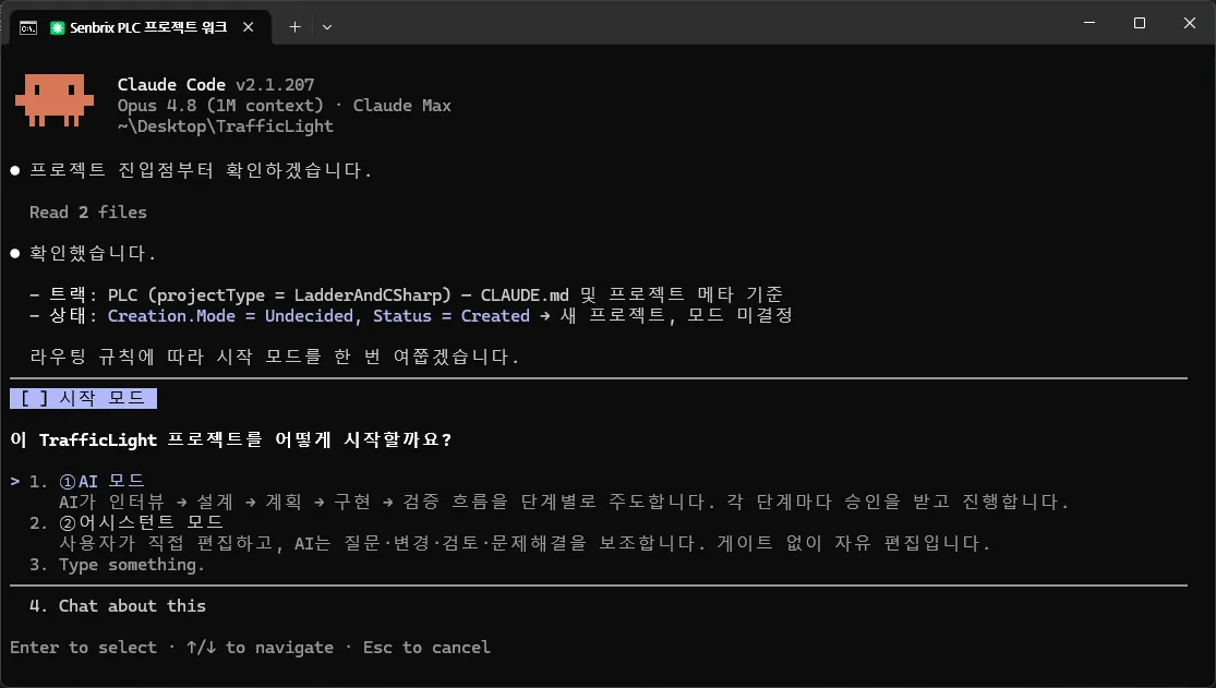
Pick assistant mode and nothing happens. An empty project opens. You register symbols and draw ladder the way we did in Part 3. This is Senbrix without AI. I know that more people on the shop floor are wary of AI than not. For those people, this tool cannot be a thing that is useless without AI. That said, this mode is not a wall against AI either. Even a project started this way can hand the AI a ladder edit or a review when you want one. That is why the mode is called assistant.
Pick AI mode and the flow in this post begins. But the mode only lives while the project is being built. Once verification finishes it switches to assistant mode on its own, and from then on the project is the same as one you started plain. The AI does not keep holding the wheel.
I put this fork first on purpose. In this system, AI is something you opt into, not something you need. Skip it and you have an ordinary PLC development environment. Choose it and you get the rest of this post.
How You Make It Do It
AI mode builds a program in five stages. But the five are not all the same kind of thing. The first three are stages a human walks through and approves. The last two are stages where the AI closes out an approved design on its own.
Interview → Design → Plan   ← a human steps in and approves
Implement → Verify          ← the AI closes it out
This is not a setup where you say “build me a traffic light” and ladder pours out. The interview closes the requirements and a design document gets written. Only after an implementation plan is in place does the ladder get written, and once written, it gets verified.
There are gates between stages. Design and plan both stop in a waiting-for-approval state once the document is done. A human reviews and approves, and only then does it move on. Toss out a “go ahead” somewhere mid-conversation and that is not read as blanket approval for every remaining stage. It passes the one gate that is currently up. There is no way around.
Progress lives in a file, not in the AI’s memory. A progress.json in the project folder records which stage you are in, what is done, and what is left. If the chat session drops, or you come back days later, the AI reads this file and picks up at the same spot. Because of this file, resuming does not mean starting the questions over. The editor’s AI page shows the file as a progress board, and that is where a human sees how far things have gotten.
The traffic light started with the interview. I described what I wanted to build, and the AI came back first with a breakdown of what an intersection signal controller is made of. Then at every fork it laid out options and asked. The big questions, boiled down:
| Category | What it asked | My answer |
|---|---|---|
| Sequence | Which order for the four phases: leading left turn (recommended), lagging left turn, or split phasing | Leading left turn |
| Equipment layout | How to split the program: common, phase sequencer, north-south output, east-west output, safety interlock, five blocks proposed | Confirmed as is |
| Operating mode | How to switch between auto, night, and manual: panel selector (recommended), time-of-day schedule, or button cycling | Selector switch |
| Timing values | How long for yellow, all-red, and pedestrian intervals | Confirmed at the manual’s standard values |
| Safety and alarms | On top of conflict lockout and minimum yellow, where does it fall when a fault is detected | All-direction red flash, until a human resets |
Each recommendation came with a reason. Leading left turn had a note saying it is closer to the Korean standard and handles queued left-turn vehicles well. I took it. Most answers went like that, a click on one card out of a few.
Once the skeleton was set, the questions drilled into each block. Every block has a fixed set of slots to fill. When is it allowed to run (permission). What triggers it (command). What does it put out (output). What state is it in now (status). How does it notice a fault (fault). How does it talk to other blocks (interlink). A block does not close until all of those are filled. Look at the progress board capture below and you can see those slots laid out for each block.
The numbers were not invented either. When it came time to set the yellow interval, the AI went and searched the National Police Agency’s manual on traffic signal installation and operation. For a crossing width of 20 to 25 m at 50 km/h, yellow is 3 seconds; 30 to 40 m, 4 seconds; over 45 m, 5 seconds. All-red is 1 to 2 seconds. Minimum pedestrian green is 3.2 seconds plus the crossing length divided by walking speed. It proposed those standard values with the source attached, and all I did was confirm.
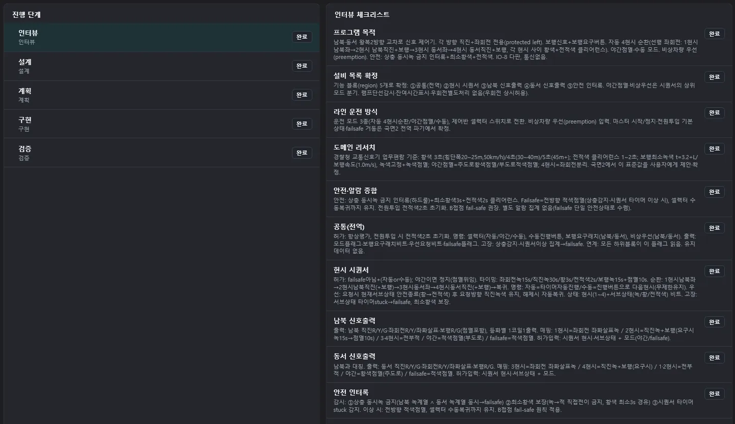
When the interview closes, the AI writes the design document and stops for approval. One design.md holding the state machine, the signal head table, and the safety guards. The human sits in the seat that reads it and signs. I did not just stamp it and move on, but that story belongs in the section on what got caught.
Design approved, next comes the plan. It breaks the design into implementation units, writes down what gets built in what order and what each piece is verified against, then stops again. Two stops before the AI touches ladder. The documents do not scatter into the chat. The design stays in the project as design.md, the plan as plan.md. Implementation and verification, as I said, the AI closes on its own, and once verification is done AI mode steps down and the project becomes an assistant-mode project.
Each approval I sent in this flow was two characters long. 승인 (approve) for the design, 진행 (proceed) for the plan. Short, but without those two words the workflow stands still right where it is.
That is the procedure seen from the outside. So what came out?
What Came Out
The deliverables first. 85 rungs of ladder, 59 symbols, five function blocks, four IO-8 boards, one design document and one implementation plan. Not a single line of C#. The AI judged that a traffic light is nothing but conditions, timers, and state transitions, so ladder alone would do, and it left App.cs empty. Part 3 split the roles of ladder and C#, and this example landed on the side where C# has no job. Not writing code where no calculation is needed is a judgment too.
The Design Document
Copying the whole design document would be dull, so here are pieces. First, operating modes. The three selector inputs get judged every scan.
Exactly one of auto, night, or manual must be on. Zero means a broken wire; two or more means a wiring error. Either way it is treated as a fault and drops to all-direction red flash.
The design even accounts for a rotary selector being a physical thing that closes only one position at a time. The instant no contact is closed, it suspects a broken wire. That is the kind of defense someone who has had wiring yanked out on site would write.
Next, the sequencer. The skeleton of the four-phase cycle came out as a state transition diagram.
[INIT] all-red 2 s
   │
[P1G]─yellow req→[P1Y]─3 s→[P1AR]─branch→[P2G]─yellow req→[P2Y]─3 s→[P2AR]─branch→
 NS left green    NS left yellow  all-red   NS through green  yellow    all-red
→[P3G] EW left … →[P4G] EW through … →[P4AR]─branch→(back to P1G)

yellow req = (auto AND phase timer expired)
          OR (manual AND advance button rising edge)
          OR (emergency preempt AND minimum green 5 s elapsed)
The green-to-yellow condition is bundled into one. In auto the timer pulls the transition, in manual the button, under emergency preempt the request. And whichever path you take, 3 seconds of yellow and 2 seconds of all-red cannot be skipped. The state machine simply has no road from green straight to red. Minimum yellow is not bolted on as a watchdog; the road itself was laid that way.
The timing values confirmed against the manual during the interview became the timer settings as they were.
| Interval | Time |
|---|---|
| Left turn green | 15 s |
| Through green | 30 s |
| Yellow | 3 s |
| All-red | 2 s |
| Emergency preempt minimum green | 5 s |
| Pedestrian green steady / flashing | 15 s / 10 s |
Emergency preemption was solved as states too. A request coming in does not cut in immediately. The current phase finishes normally through yellow and all-red, then it moves to through green for the requested direction and holds there. When the request clears, it merges into that through phase’s yellow and returns to the normal cycle. Mode changes work the same way; they are only accepted during all-red. Any switch goes through a moment where every direction is red.
Signal outputs turn on by state alone. North-south through green is on when the current state is P2G. It does not look at transition conditions. Set it up this way and later, when someone doing maintenance asks why this lamp is on, the answer is always the same one. Because we are in this state.
Pedestrians are only served on request. The button is a momentary contact, so the press is latched with a seal-in and released at the all-red that ends the matching through phase. No request, and the pedestrian head stays red while vehicle green runs as usual. Pedestrian green is 15 seconds steady, then 10 seconds flashing to finish. The formula lifted from the manual sits right here.
Safety is watched in the last block. It gathers the north-south green-family heads and the east-west green-family heads, and if both are on at once it calls a conflict. By design the states are mutually exclusive, so normally this never happens. The design document says why the watchdog is there anyway. If it did happen, the hardware or the wiring has failed, and this watchdog is the last thing that drops everything to all-direction red flash.
At the end of the design document there is a decision log. Why the states were split into 17. Why north-south is served first when emergency preempts arrive at the same time. Why a stalled sequencer is not watched by time. I liked the reasoning on the last one. In manual mode and under emergency preempt, waiting indefinitely is normal, so a time watchdog would throw false alarms. Instead it only catches the abnormal case where every state bit goes off. Seventeen decisions like this sit there, numbered. When whoever maintains this program later asks why it was done this way, the document answers.
Ladder, Symbols, Wiring
The ladder came out in five blocks. Common, sequencer, north-south output, east-west output, safety. The same five confirmed in the interview. Below is a screen with only the east-west output expanded. The other four are collapsed with just their headers showing, and the row numbers in the expanded block run past 250.
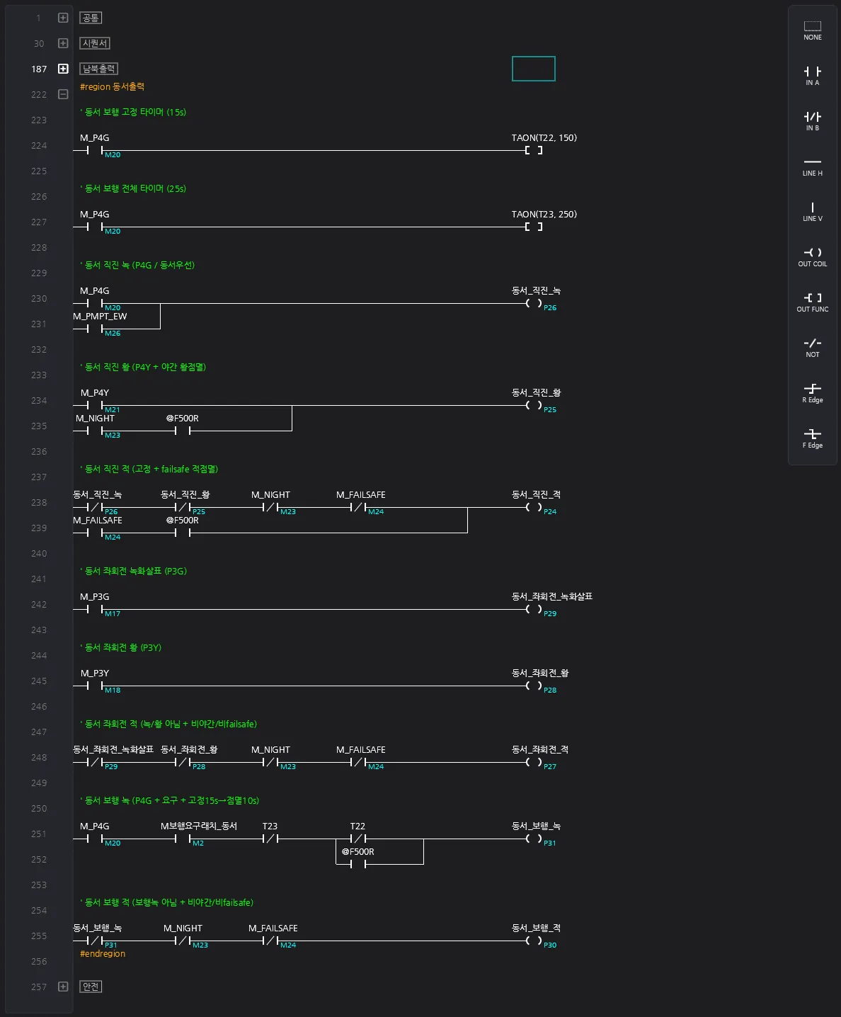
Every signal head gets a rung. Green and yellow take the state bit directly, as I said above. East-west through green is the M_P4G rung (with M_PMPT_EW alongside for east-west preempt), and yellow is the M_P4Y rung. Red was written differently. Not green and not yellow means red, so the through-red rung is built from the green and yellow contacts above it as NC. When maintenance asks why it is red, the answer is the rung right above.
Night mode and failsafe layer a flash on top. In night mode a (night ∧ @F500R) branch on east-west through yellow makes the main road blink yellow, and in failsafe the through red blinks the same way. @F500R is a special relay that toggles on and off on a 0.5 second cycle.
59 symbols were registered. Their names carry roles, not addresses.
셀렉터_자동    P0    공통/셀렉터    자동 모드 선택(NO)
남북_직진_녹   P18   남북/직진      IO8 #1 OUT2
동서_보행_적   P30   동서/보행      IO8 #4 OUT2
Those three are 셀렉터_자동 (auto selector), 남북_직진_녹 (north-south through green), and 동서_보행_적 (east-west pedestrian red). The path column groups symbols by equipment. It splits into common, north-south, and east-west, and under those into through, left turn, and pedestrian. The description column of every output symbol carries which IO-8 board and which channel, as is. 남북_직진_녹 is OUT2 on IO8 #1. Inputs get Read access, outputs and internal M bits get ReadWrite. This screen is what I meant when I said the columns made for humans to read become a map for the AI exactly as they are.
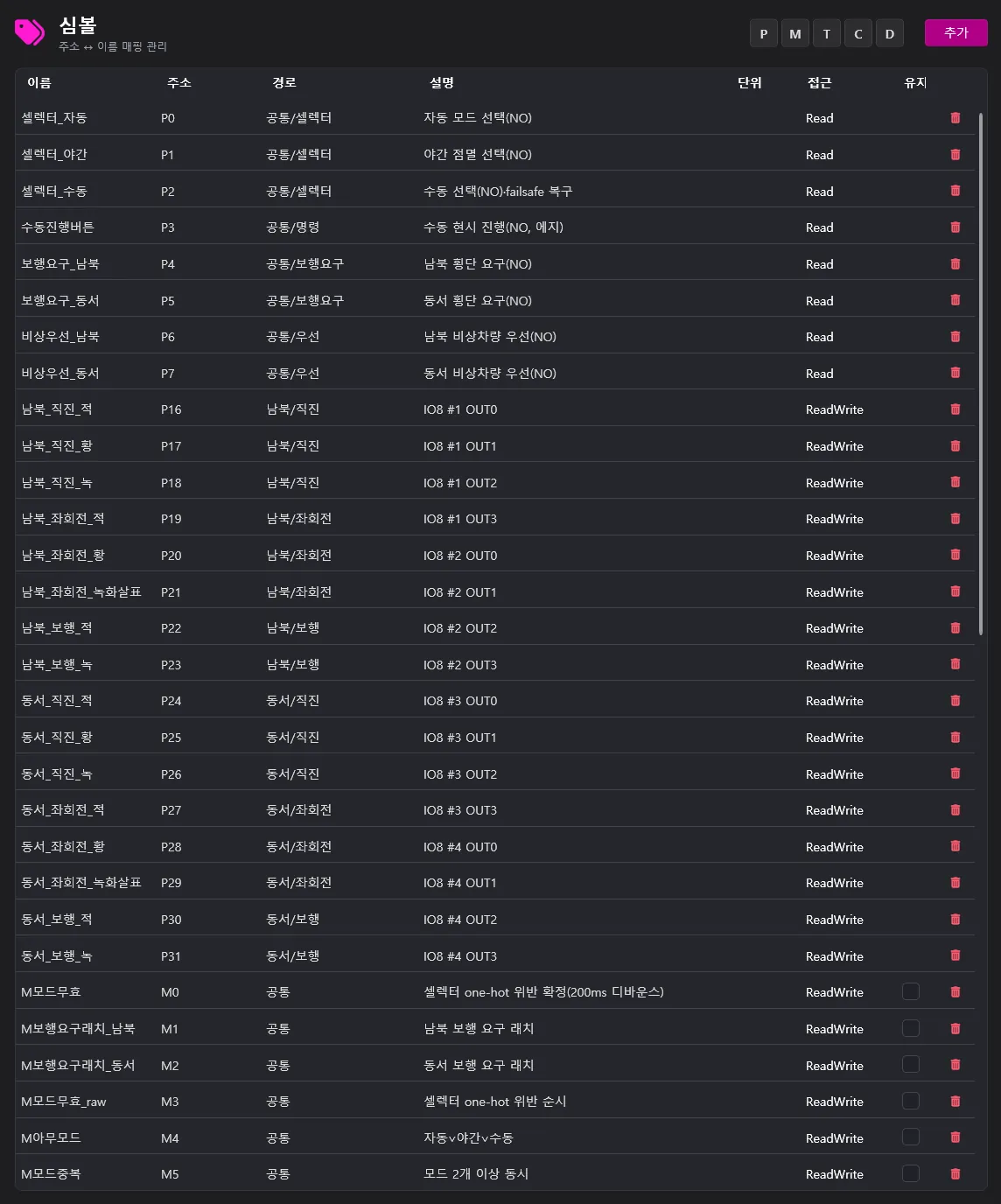
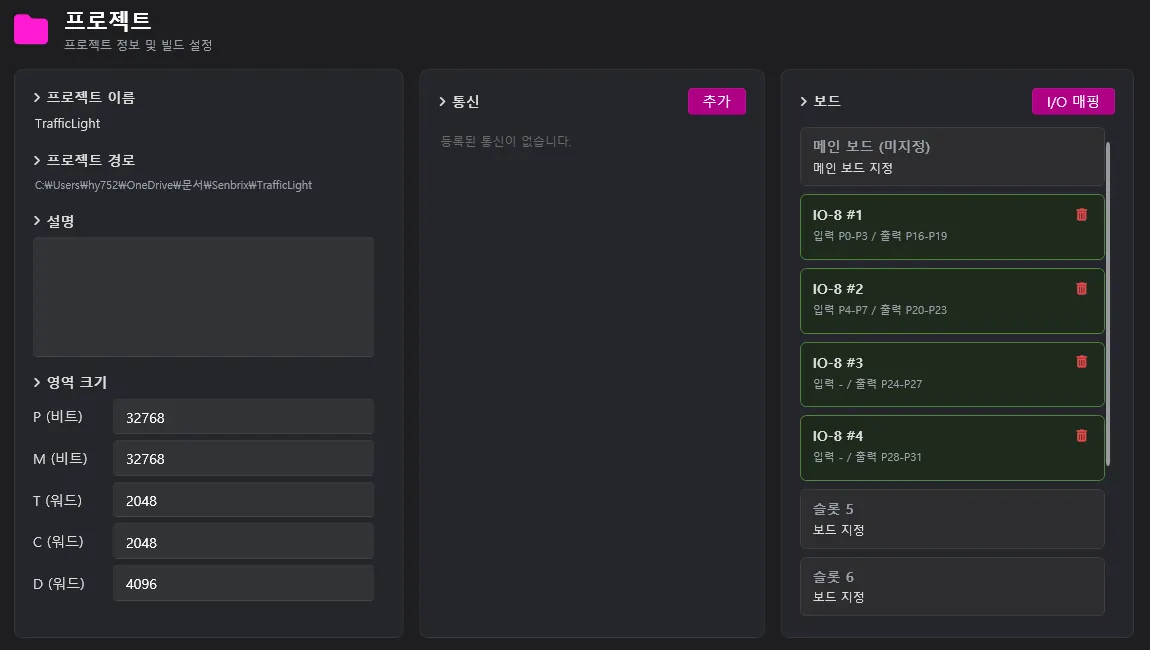
Wiring is set by the board configuration on the project page. Four IO-8 boards, 8 inputs and 16 outputs. The inputs go into the first two boards (P0 to P7): three selector positions, the manual advance button, two pedestrian calls, two emergency preempts. The outputs, sixteen heads (three through colors, three left-turn colors, and two pedestrian colors per direction), are spread across four boards (P16 to P31). So the last two boards use outputs only, no inputs. Communication is empty. There is nobody to exchange values with, so for the same reason C# was left empty, no comms were attached either. When building the panel, wire it by this address layout and the channel numbers in the symbol descriptions.
That is everything that came out. For a handful of words, it is a lot. So now for the real subject of this post. Why does it work?
Why an AI Can Write Ladder
The short answer is a DSL. An intermediate language agreed between the AI and the ladder tool, a text notation that goes back and forth with the ladder grid without loss. Why is that needed?
Ladder is a picture. But as we saw in Part 3, the actual data behind the picture is a grid. Each cell has a position, a type, and a code. Chain cells horizontally and you get series; tie them with vertical lines and you get parallel. What the editor draws is a render of this grid, and saving and deploying both work on the grid data.
You could hand the AI the grid as is. The grid serializes to JSON, so pass the cell list wholesale and take a cell list back. But this is the kind of work an AI does badly. In a grid the logic is not in any one cell; it is in the arrangement of cells. Which row, which column, which lines connect them, that is the circuit. An AI is a thing that handles text, and the reason it writes code well is that code is text. Picking a circuit out of a pile of coordinates is a weak spot, and so is placing written logic into coordinates and drawing the lines. Insert one parallel branch and every coordinate on the rows below shifts. One cell off and it is a different circuit.
So I built a DSL between the two. Text with the layout stripped from the grid and only the logic left. Series is line order, parallel is a branch block. No coordinates anywhere. Pull one rung from the traffic light ladder and it looks like this. The picture the editor draws.
  M남북녹계열   M동서녹계열                     M충돌감지
────┤ ├──────────┤ ├───────────────────────────( )
Here M남북녹계열 (north-south green family) and M동서녹계열 (east-west green family) feed M충돌감지 (conflict detected). The same rung written as DSL looks like this. The words of the design, the text of the DSL, the picture in the editor, all one line.
RUNG "상충 동시녹 감지"
  IN_A M남북녹계열
  IN_A M동서녹계열
  COIL M충돌감지
END
The rung name reads “conflicting greens detected”. One contact, one coil, one line of text each. Parallel branches work the same way. An OR circuit stacked vertically becomes a branch block in text.
  셀렉터_자동                                    M아무모드
────┤ ├────┬──────────────────────────────────( )
  셀렉터_야간│
────┤ ├────┤
  셀렉터_수동│
────┤ ├────┘
RUNG "모드 선택"
PARALLEL
BRANCH
IN_A 셀렉터_자동
BRANCH
IN_A 셀렉터_야간
BRANCH
IN_A 셀렉터_수동
END
COIL M아무모드
ENDThat one is “mode select”: 셀렉터_야간 (night selector) and 셀렉터_수동 (manual selector) join the auto selector to drive M아무모드 (any mode on).
So who does the layout? The converter. When the AI writes DSL it goes through a syntax check first, and if that passes, the converter seats the cells, draws the lines, and produces the grid. In the editor it shows up as a picture. The reverse works too. Pull a drawn ladder out as DSL, edit it, put it back. Whichever direction you go, nothing is clipped or mangled. This lossless round trip is what lets an AI take over a ladder a human drew as a picture and touch it up as text. The human always sees the picture; the AI always writes the text.
That is also why a human can step into the middle of the AI’s work. Every time the AI edits ladder, it rereads the current state in full and writes on top of it. If a human fixes a few rungs directly in the editor, the next AI turn reads those fixes and continues from them. It does not overwrite the human’s hand. @row anchors hold each rung in place, so even after a trip through text, the comments, watches, and rung placement a human added come back intact. A human and an AI can take turns on one ladder without trampling each other’s work.
Addresses barely show up in the DSL either. There is no P0 in the text above; there are symbol names like 셀렉터_자동 and M남북녹계열. Back in Part 3, covering symbols, I wrote that the address, path, and description columns are not there just for people’s convenience; the AI uses that symbol information as its basis when it builds and analyzes ladder and code. That sentence gets executed right here. The path and description on a symbol are the AI’s map to which piece of equipment this signal belongs to and what it does. A scheme made for humans to read works on the AI as is.
Seen that way, the DSL is not a detour built because an AI cannot handle coordinates. It is the passage that lets a human and an AI hold the same ladder in turns.
Use Only What You Know
Being able to write in the DSL and writing it correctly are different problems.
Our ladder notation is not in the AI’s training data. Neither is the function list or the address scheme. What an AI does in that situation is predictable. It makes something up as if it knew. The problem is that what it makes up looks plausible. A function that does not exist, an address written wrong. These look fine on the surface and might even pass the build. Fakes the build cannot catch.
So I nailed down one rule. Use only what the docs confirm. Senbrix ships with built-in documents covering ladder grammar, the function list, the address scheme, and symbol rules, and before the AI writes anything into ladder it has to look it up in these documents and confirm it actually exists. If it is not in the docs, it does not count as known. Instead of inventing, it says it does not know and asks.
The docs hold more than grammar. Safety rules and design methods are in there too. How to arrange signals so a lost input fails to the safe side. One coil per output, never more. A machine must not restart on its own just because the emergency stop was released. The standard form for moving a state machine into ladder. Write down the things the shop floor takes for granted, and the AI uses that common sense as its basis when it designs. Ask where the traffic light’s safety skeleton came from and the answer is these documents.
The lookups leave a trace in the plan. The traffic light plan got a table with a source for everything it intended to use.
| Used | Notation | Source |
|---|---|---|
| Timer | TAON, 100 ms units | Grammar doc |
| Special relays | @BEGIN (first scan), @F500R (flash) | Symbol doc |
| Safety principle | Absence of signal fails safe | Safety doc |
Items without a source: none.
If the source table is the first device, the second is implementation items. For each block in the design, implementation items are created and pinned into progress.json ahead of time. Each item is bundled with which section of the design it rests on and what it is verified against. The implementing AI cannot add items to this list; it can only close the registered ones one at a time. The traffic light got items like this for all five blocks. Two of them:
| Item | Basis | Closing condition |
|---|---|---|
| Phase sequencer | Design §5.1 | 17 states, full transition table cross-check, build passes |
| Safety interlock | Design §5.4 | Conflict detection, ghost state detection, placed last, build passes |
Why is this needed? To stop the case where the safety interlock is left as a TODO and marked done. On site, an omission is an accident. With items pinned ahead of time, anything skipped stays open, and anything filled with a hollow shell gets caught in the cross-check against the design.
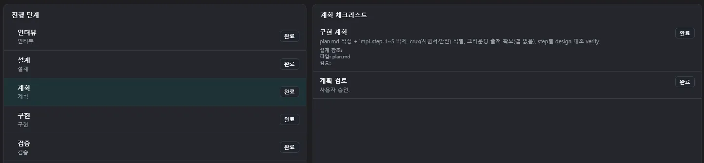
One blocks inventing, the other blocks skipping. Both devices go into the plan, and the plan has to be approved before implementation starts.
What Got Caught
There are several layers that filter what gets built. Each layer catches something different, and on this traffic light each layer actually caught one thing. I will go by layer, not by time.
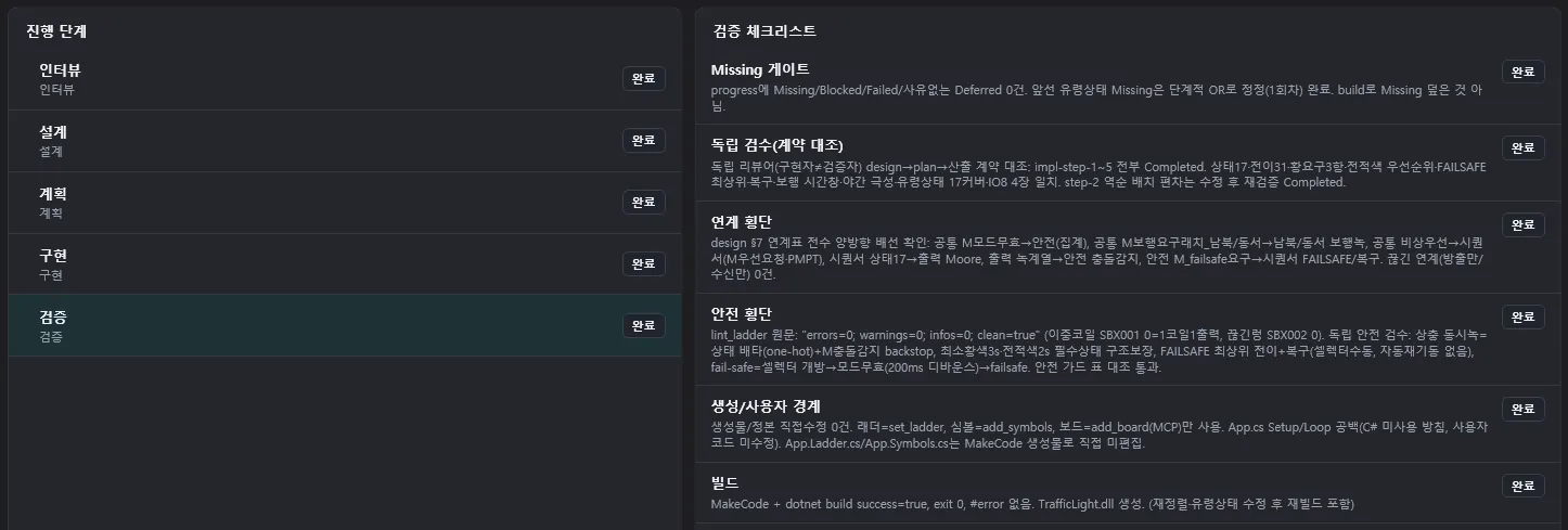
The machine is the first layer. The build catches grammar. On top of that runs a ladder structure check. Broken rungs that never reach an output, outputs doubled up on the same coil. The machine sweeps for wiring problems like these. This check also runs on save in the editor, so anything caught while you are still writing shows up as a badge.
The second layer is cross-checking. A review runs that matches the written ladder against the design and plan documents. In the previous section, every implementation item had “what to verify against” pinned in advance, and that scoring sheet is what actually runs here. The criteria are set before writing and the scoring happens after. This review runs separately from the flow that did the implementing. Grade your own work and you go easy on it, so the verifying side reads the design and plan from scratch and matches them against the output.
One thing got caught here. The plan required the state transition rungs to be placed in reverse order. Later states’ transitions go on top, and there is a reason. If the transition rungs line up in execution order, the moment conditions overlap, a state can skip two steps in one scan. The implemented ladder, against this requirement, was lined up in execution order. The build passed and the structure check was clean. Grammar and wiring were both fine. Only the review against the plan caught it, and the item did not close until the four transition rungs were rearranged.
A human is the last layer. This is the story I held back in the section on how you make it do it. When the design document stopped for approval I did not just approve; I went through it. Two things stuck out.
One was the night mode signal table. In night flash the main road, east-west, should flash yellow, but the table had it flashing red. Implemented as is, the main road would have been flipped into a stop signal. The other was selector switching. When you turn a rotary selector, every contact drops out for an instant. Judge that instant as a broken wire and every mode change becomes a fault. I sent it back with a note to allow some time in the judgment. While I was returning it I added one decision. Even when an emergency preempt comes in, do not kill a green that just came on; hold it at least 5 seconds. You cannot build an intersection where the green goes off the moment it comes on.
The AI accepted all three and came back with the design fixed. The night table was corrected and the judgment delay went in. Minimum green time was added to the state machine too. I checked again, and the approval I sent was one word.
승인
Line up what each layer caught. The build caught grammar, the structure check caught wiring, the document cross-check caught a broken promise. Judgment errors were caught by a human. The night signal table was a design error with perfectly fine grammar and wiring, so it never even reached the machine. No single layer can stand in for the rest, so they stack.
The Human Holds Control
To sum up, there are three points in this flow the AI cannot cross on its own.
Design approval. Plan approval. And last, deployment.
The first two you have already seen. A document stops for approval, a human reads it, sends it back if needed, it gets fixed, and only an approval moves it on. The last one, deployment, is the spot covered in Part 4. The Deploy button that puts the built app onto the hardware is in the editor, and a human presses it. There is no path by which AI-written ladder lands on a machine without a human checking.
A rejection does not mean the workflow failed. The moment I sent back the night signal table is exactly the proof that this structure works. It stopped where it was built to stop, and it was fixed along the path left for fixing.
Once verification is done, AI mode itself steps down. Back to the fork I mentioned at the start. This project is now the same as one started plain, and you open the ladder and keep drawing by hand. You can call the AI back too. That AI is an assistant. The creation is over, and it has come down to the seat where it does the edits and reviews a human asks for.
So the accurate way to say it is this. The AI does not write the ladder; a human writes the ladder with an AI. What the AI supplies is a draft and speed. Judgment and completion stay with the human.
Wrapping Up
When it was over I opened the session log and counted what I had typed. The messages I entered on the keyboard while building this project came to four lines. One instruction to start, one design rejection, approve, proceed. Everything else was a click on a card. What came out was an 85-rung traffic signal controller.
A few words in, a controller out. Huh. It actually works.
I can answer why now, too. I built a language so ladder can be written as text, and I fenced the AI in to use only what the docs confirm. I set it up so a human approves at every stage. Those three are the whole of it. No magic trick.
In Part 1 I wrote: if it writes code this well, why not ladder? I have the answer. It can. But the AI does the writing, and the human does the directing, the filtering, and the finishing.
Next Part
That was the story of an AI writing ladder. The next part is about an AI looking into a PLC that is running. It reads values, pinpoints why something is stuck, and goes as far as fixing it. Only within the bounds a human allows, of course.
Comments
Enter a nickname to leave a comment, or sign in with Google or GitHub.