
We built a horse-riding machine controller using the 3.5-inch RP2350 touch LCD.
- 12 operating modes: one manual mode and 11 program modes
- 10-stage speed graph: speed levels 1-10 for each stage
- 6-60 Hz inverter control: converts each speed level to a frequency
- RS485 Modbus RTU: START, STOP, and speed commands with operating-status checks
- RP2350 dual core: separates motor communication from touch-screen processing
- 480×320 ST7796 LCD: running-horse animation with partial screen updates
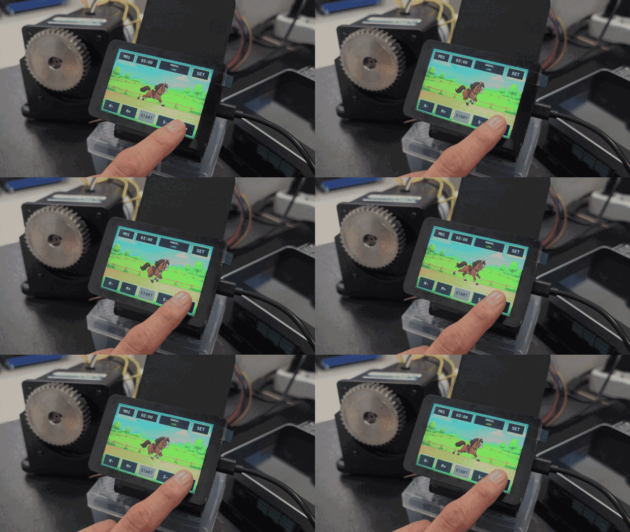
RP2350 horse-riding machine controller specifications
| Item | Specification |
|---|---|
| MCU | RP2350 dual core |
| Display | 3.5-inch ST7796, 480×320 |
| Touch | FT6336U capacitive touch |
| Operating modes | M01-M12 |
| Manual mode | M01 |
| Program modes | M02-M12, 11 total |
| Program stages | 10 stages per mode |
| User speed | LV01-LV10 |
| Inverter frequency | 6-60 Hz |
| Communication | RS485 Modbus RTU, 19,200 bps, 8N1 |
| Screen processing | One RGB565 back buffer with changed-region transfers |
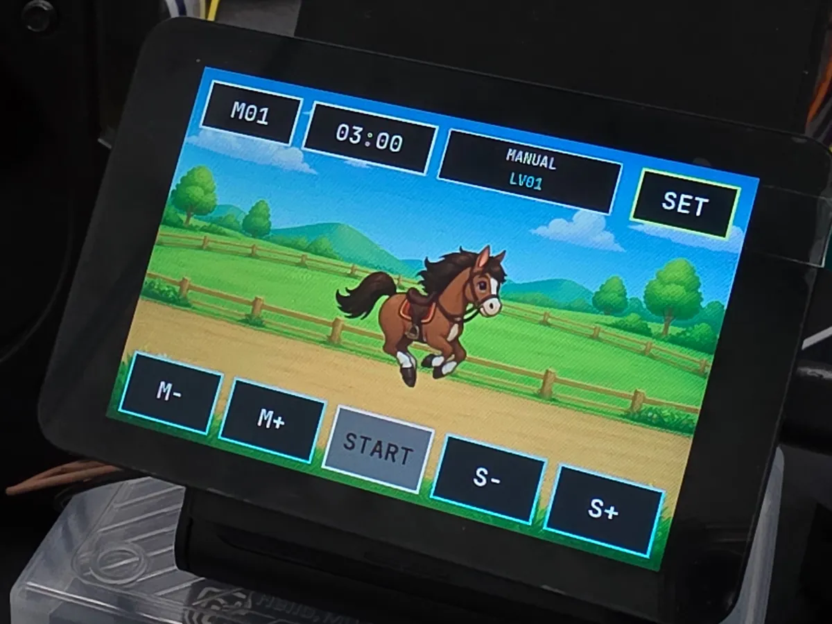
M01 manual mode: change speed directly from 1 to 10
M01 is the manual operating mode.
The S- and S+ buttons on the home screen change the speed through levels 1-10.
| Screen speed | Inverter command |
|---|---|
| LV01 | 6 Hz |
| LV05 | 30 Hz |
| LV10 | 60 Hz |
The user selects only LV01-LV10 on screen,
and the RP2350 converts that value to a 6-60 Hz frequency and sends it to the inverter.
M02-M12 program modes: automatic speed changes over 10 stages
M02-M12 are program operating modes. Each mode has 10 speed stages.
total ride time ÷ 10 = operating time per stage

Example: 10-minute ride
→ 1 minute per stage
→ apply the next speed every minute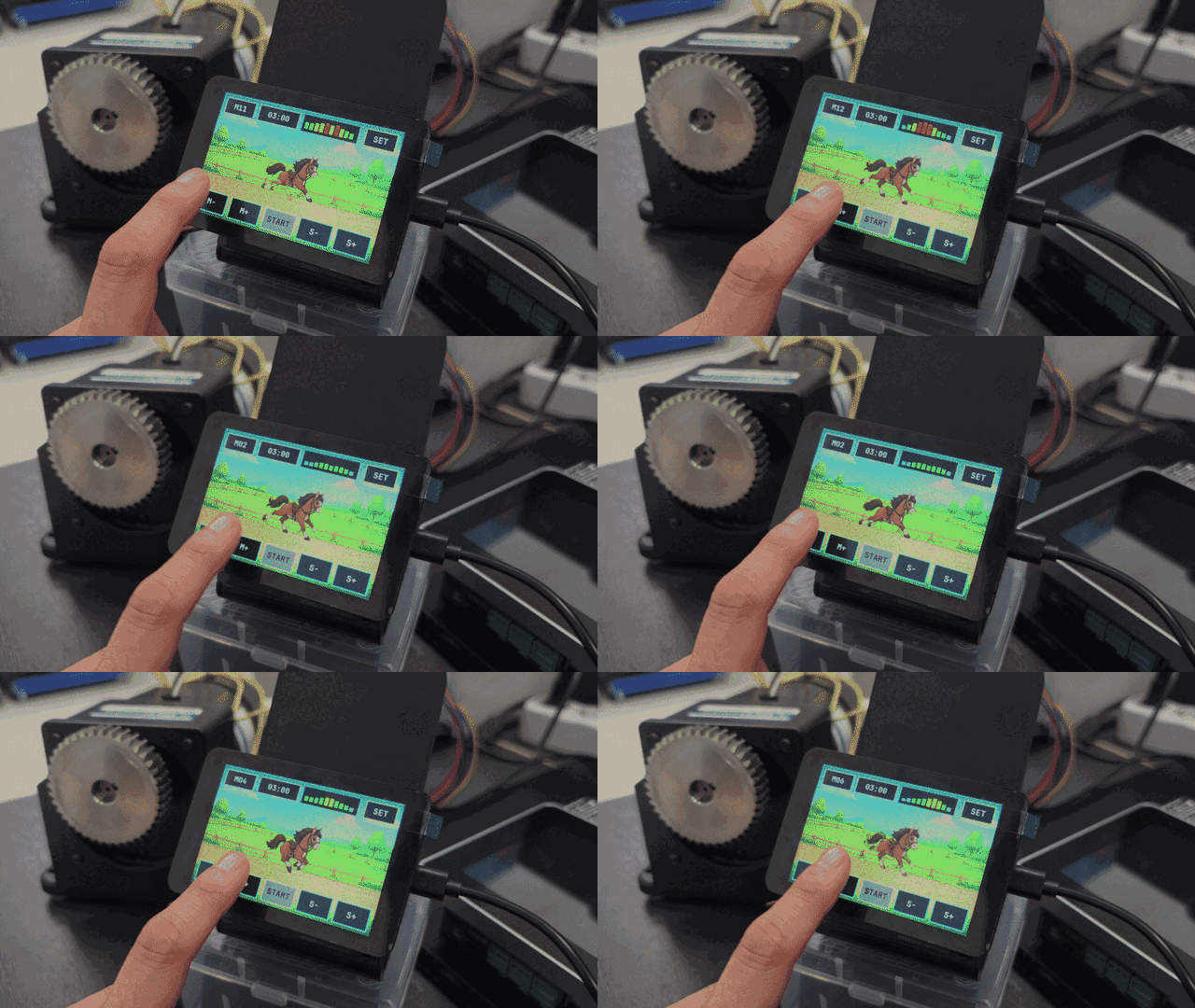
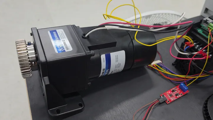
Connecting the RP2350 touch LCD, inverter, and motor
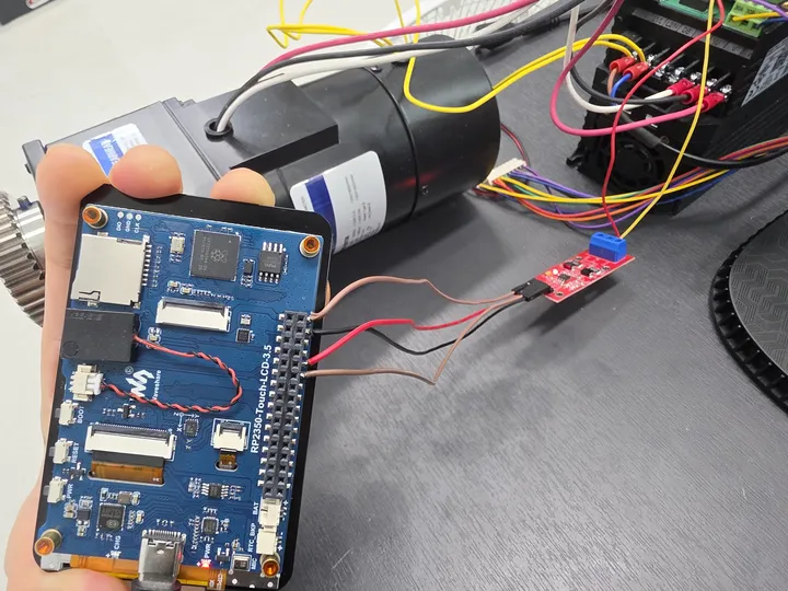
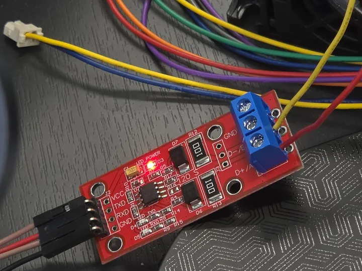
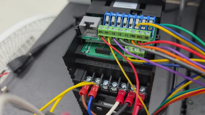
The RP2350’s 3.3 V UART must not be connected directly to the inverter’s A/B terminals. An RS485 transceiver is required between UART and RS485 to convert the voltage and signaling method.
The seven-step process after START
- Confirm the
STARTinput on the touch screen. - Confirm that the inverter is stopped.
- Write the selected speed to the S05 frequency command.
- Read S05 back and confirm that the value was applied.
- Write the FWD run command to S06.
- Check the operating status and actual frequency every 500 ms.
- Change the screen to
RUNNINGafter operation is confirmed.
The maximum response wait for one Modbus request is 200 ms. If the operating state and actual frequency are not confirmed within 10 seconds after START, the controller sends STOP. The controller also sends STOP when status polling fails three times in a row.

RS485 processing and touch LCD processing
The RS485 implementation exchanges only the START, STOP, mode, and speed commands with the touch LCD implementation.
Even during the maximum 200 ms wait for an inverter response, the touch LCD implementation continues handling touch input and screen processing.
Reducing screen flicker with a 307,200-byte back buffer
The size of one 480×320 RGB565 screen is:
480 × 320 × 2 bytes = 307,200 bytesInstead of using two screen buffers, we used one 307,200-byte back buffer. When a button, the time, the graph, or a horse frame changes, only that rectangular region is transferred to the ST7796.
The horse animation consists of three PNG frames. Before compositing the next frame, the controller restores the background where the previous horse was displayed, so no black rectangle remains.
The implementation details are covered in RP2350 TFT LCD animation and ST7796 partial screen updates.
A communication STOP is not an emergency stop
S06 STOP is a Modbus communication command. It does not cut power, and it cannot stop every fault involving a broken communication line, an RP2350 failure, or an inverter failure.
A horse-riding machine carrying a person requires separate devices for:
- A hardware emergency-stop switch
- A motor power cutoff circuit
- Mechanical position and limit interlocks
- Rider departure and overload detection
- Stopping-distance tests under actual equipment conditions
Summary
The six core elements of this horse-riding machine controller are:
- RP2350 Touch LCD 3.5
- One manual mode and 11 program modes
- A 10-stage speed profile for each mode
- Conversion of speed levels 1-10 to 6-60 Hz
- RS485 Modbus inverter START, STOP, and status checks
- Core 0 for communication and Core 1 for the screen
When a horse-riding machine, rehabilitation device, or riding simulator needs mode, time, speed, and inverter control, the touch UI and RS485 communication can be configured together for the equipment specifications.
Contact
- Email: [email protected]
- Instagram: https://www.instagram.com/going.sen/
- Website: https://intosen.com/kr/consult/
Comments
Enter a nickname to leave a comment, or sign in with Google or GitHub.