
We controlled an inverter motor over RS485 Modbus RTU and plotted the actual speed read back from the inverter as a graph on an RP2350 touch LCD. From the screen you can send RUN/STOP, change the speed, and watch the commanded value, the actual response, and the communication status side by side.
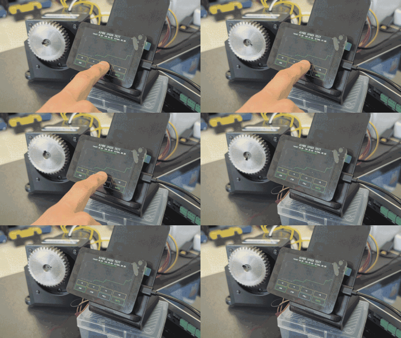
Changing the inverter motor speed from the RP2350 touch LCD while the actual speed graph updates
Motor control from the RP2350 touch LCD
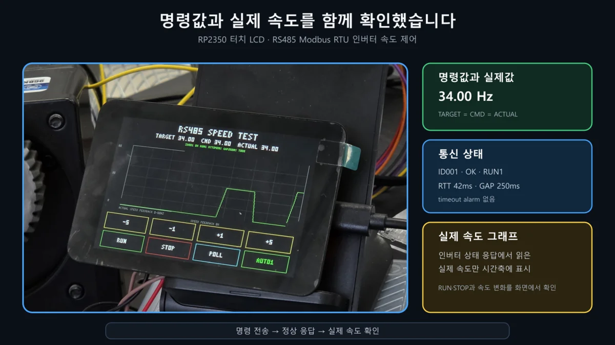
The RP2350 touch LCD showing the command value and the actual speed together
| Function | What it does on screen |
|---|---|
| RUN / STOP | Sends run and stop commands to the inverter |
| -5 / -1 / +1 / +5 | Changes the target speed while running |
| TARGET / CMD | Shows the setpoint and the command value that was actually sent |
| ACTUAL | Shows the actual speed read from the inverter status response |
| Comm status | Shows OK responses, response time, and errors |
The important part of this screen is that it keeps the target speed and the actual speed separate.
Sending a speed command does not mean the motor is running at that speed.
The maximum speed frequency is 60Hz.
How the graph is drawn on the RP2350 touch LCD
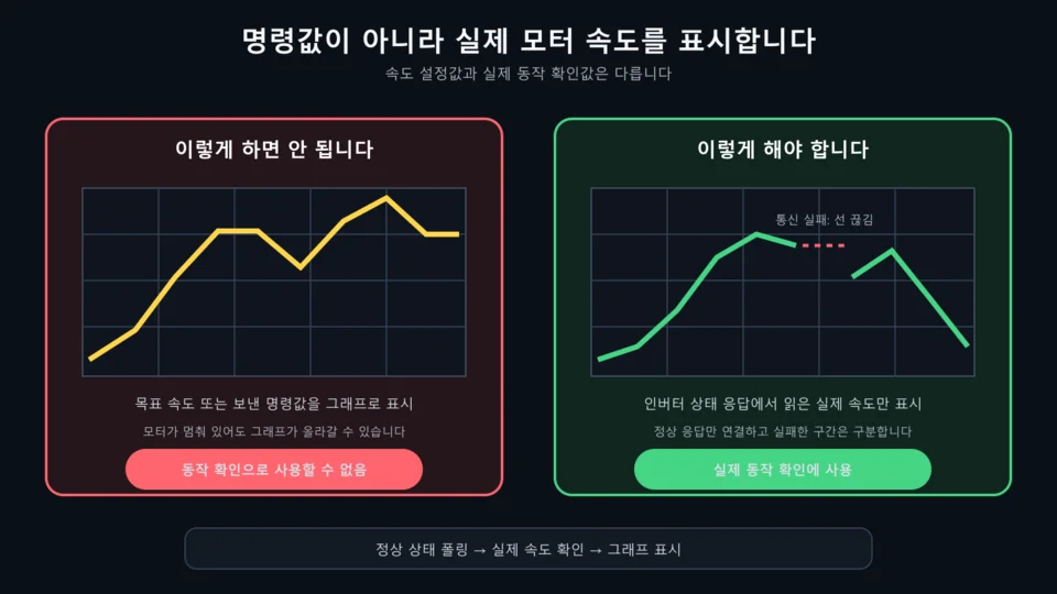
Plot only the actual motor speed read from the inverter status response, not the command value
Only the graph area is redrawn, so the buttons and the status line do not flicker while the motor is running.
Even while the user is pressing +1, -1, +5, -5 on the LCD, any gap in the actual data shows up as a gap in the line.
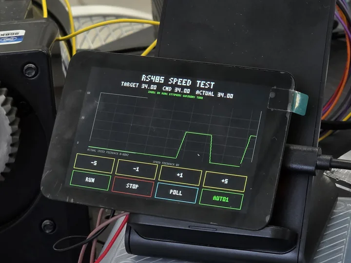
Actual speed graph and RUN/STOP/speed buttons on the RP2350 touch LCD
- Send the request.
- Read the inverter status registers back.
- Append only the actual speed taken from a valid response to the graph.
- Where there is no response or validation fails, break the line so it is distinct from valid data.
Connecting the RP2350 touch LCD to the RS485 module
The controller is an RP2350-based 3.5-inch touch LCD plus an RS485 transceiver module. The RP2350’s UART signal passes through the RS485 module, where it becomes an A/B differential signal that carries RUN/STOP and speed commands to the inverter.
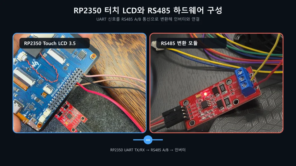
Hardware: RP2350 Touch LCD 3.5 and the RS485 transceiver module
Full wiring from the touch LCD to the motor
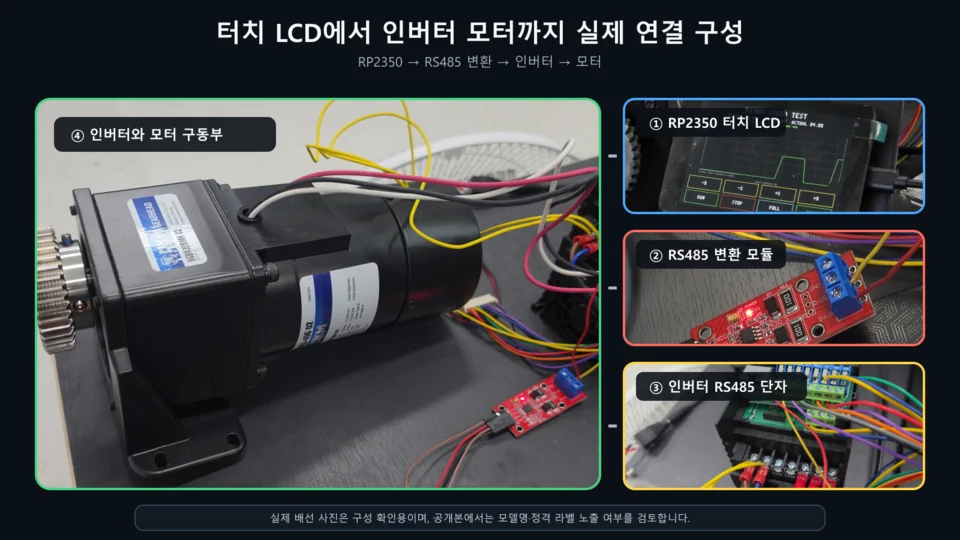
RP2350 touch LCD → RS485 module → inverter → motor
| Item | Applied |
|---|---|
| Communication | RS485 Modbus RTU |
| Baud rate | 19,200 bps |
| Display | RP2350 3.5-inch 480×320 touch LCD |
| Control | Inverter RUN/STOP, speed change |
| Monitoring | Actual speed, response time, communication errors |
Mistaking the RS485 echo for a real response
During testing, the same 8 bytes we had just sent came back, which made it look as if communication was working.
But for this 0x03 read of six status registers, a valid response has to be 17 bytes.
It turned out those 8 bytes were not the inverter’s status response at all. They were the request echo returned by the RS485 module.
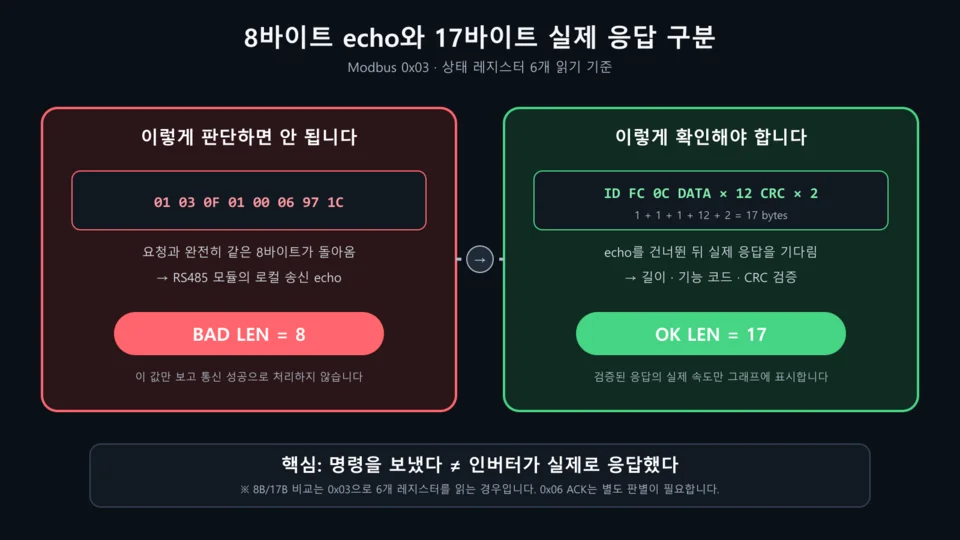
Telling the 8-byte request echo apart from the 17-byte real Modbus response
The fix:
- Detect data identical to the request as an echo and skip it.
- Check the expected response length and the CRC.
- Read the actual speed value only from a valid response.
- If there is no response or validation fails, show a communication error on screen.
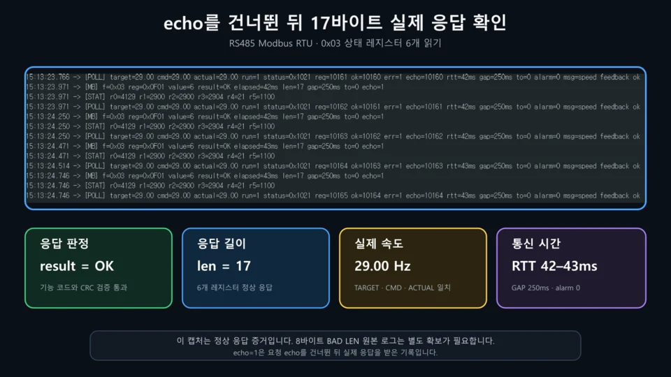
Modbus log showing the 17-byte real response after skipping the echo
This separates “the command was sent” from “the inverter actually responded.” The graph follows the same rule: it plots only the actual speed read from valid responses.
Where this applies
- Treadmills and fitness equipment
- Conveyors and transfer systems
- Pump and fan control
- Small automation machines
- Inverter status monitoring
Summary
In RS485 inverter motor control, sending a command and confirming the actual motion are two different things. This RP2350 touch LCD build adds RUN/STOP and speed adjustment, and graphs only the actual speed read from valid inverter responses.
- Inverter RUN/STOP and speed control over RS485 Modbus RTU
- Command value and actual value shown on the RP2350 3.5-inch touch LCD
- Only the actual speed from valid responses goes on the graph
- Request echo and real responses told apart by length and CRC
- Communication failures kept separate from valid data
The point is not to present the command value as the result, but to go back and confirm the inverter’s response and actual speed.
Contact
- Email: [email protected]
- Instagram: https://www.instagram.com/going.sen/
- Website: https://intosen.com/kr/consult/
Comments
Enter a nickname to leave a comment, or sign in with Google or GitHub.