
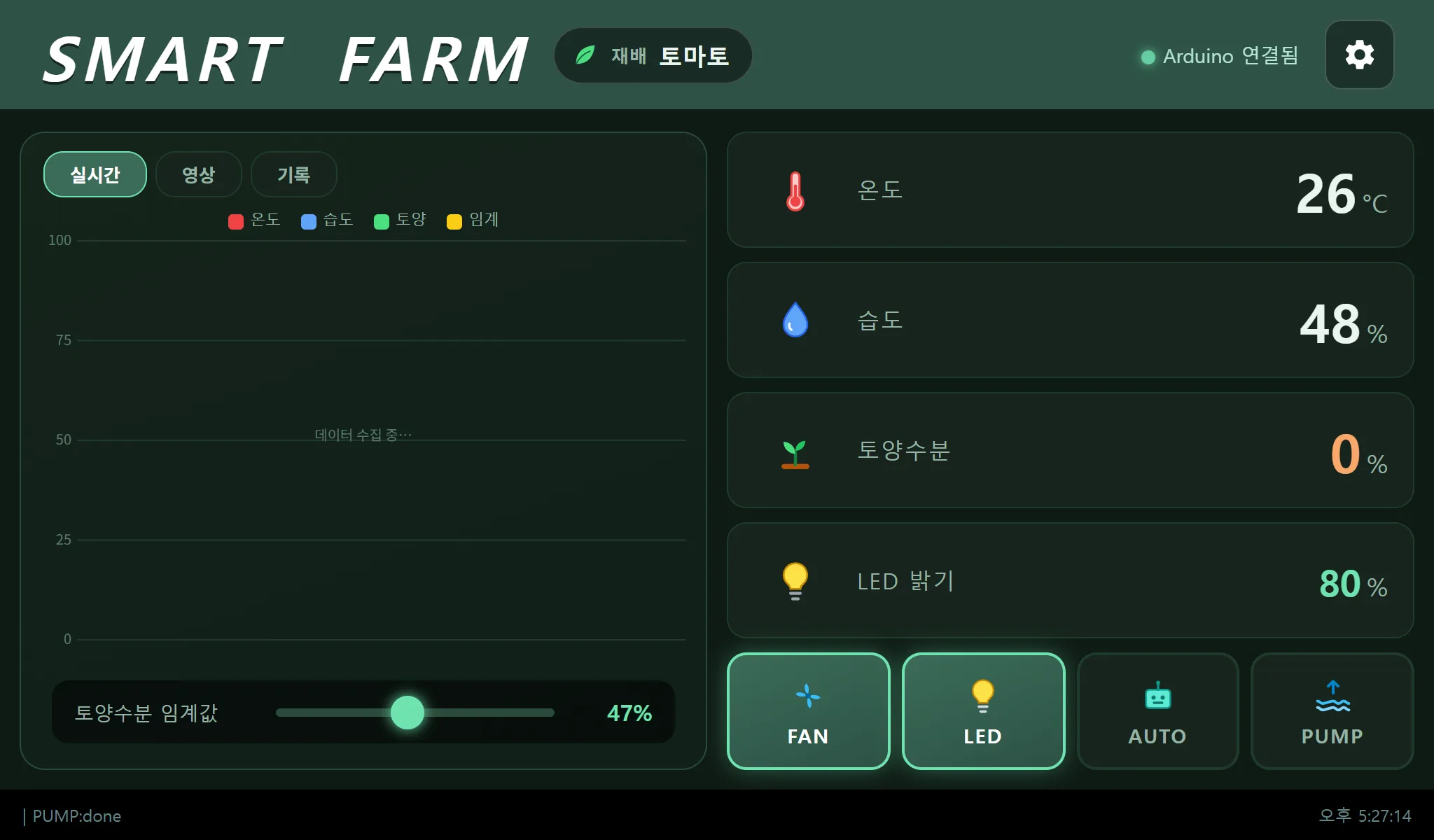
A smart farm system where an Arduino Mega handles the sensors and actuators while Senvas Touch (built on a Raspberry Pi) acts as both the Modbus RTU master and the Node.js HMI that coordinates everything. Zero dependencies, a year of CSV trend data, and a Tapo RTSP camera, all on one panel.
What we built with the smart farm HMI
This is a small indoor smart farm. Six crop presets, from leafy greens to tomatoes and strawberries, switch with a single touch, and the fan, LEDs and pump follow along automatically. The whole interface is one 1024×600 touch panel. It runs standalone, with no external server and no cloud.
The feature list:
- Live temperature, humidity and soil moisture monitoring
- Manual and automatic control of the fan, the NeoPixel LEDs and the pump
- Six crop presets (lettuce, tomato, strawberry, cucumber, pepper, basil)
- A photoperiod schedule, including a 30-minute sunrise and sunset fade
- A watering schedule, either a daily count or selected weekdays
- Live video from a Tapo RTSP camera
- A year of time-series data (CSV per minute, auto-deleted after 365 days)
The features themselves may look ordinary. What makes this post worth writing are the three troubleshooting stories behind them: the coil bit-packing trap, the black MJPEG stream, and the reason the pump kept running.
System architecture
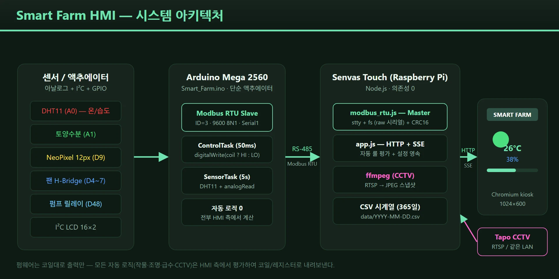
The hardware behind this smart farm system architecture is straightforward.
| Category | Part |
|---|---|
| MCU | Arduino Mega 2560 (Serial1, plenty of GPIO) |
| HMI panel | Senvas Touch (Raspberry Pi based, 1024×600) |
| Communication | USB-to-RS-485 adapter, 9600 8N1 |
| Sensors | DHT11 (temperature and humidity), analog soil moisture |
| Lighting | WS2812 NeoPixel, 12 px |
| Ventilation | DC fan with H-bridge |
| Watering | 12V pump with relay |
| Video | Tapo C200/C210 (RTSP capable) |
The software stack is just as lean. The Arduino firmware is a Modbus RTU slave, and app.js running under
Node.js on Senvas Touch is the Modbus RTU master. The browser receives live state over SSE (/events), and
the Tapo RTSP feed is converted to JPEG frames by ffmpeg and served over HTTP polling.
Three design rules need stating up front, because the troubleshooting sections only make sense with them.
- The firmware is a dumb actuator — no automation logic, no timers, no edge detection. It takes coils and drives outputs.
- The HMI has zero dependencies — the
dependenciesblock inpackage.jsonis empty. Nonpm install; upload a ZIP and runnode app.js. - All automation lives on the HMI side — behavior can change from a settings screen without reflashing the firmware.
Arduino firmware: the simpler the better
The guiding principle of the Arduino firmware is that it does exactly what it is told. Sensor values go up in Modbus holding registers, and the commands that come down as coils go straight to GPIO.
Modbus memory map
| Tag | Address | Type | R/W |
|---|---|---|---|
| Temp | HR 0x7000 | Int16 | R |
| Hum | HR 0x7001 | Int16 | R |
| Sol (soil moisture) | HR 0x7002 | Int16 | R |
| Sol_Set (threshold) | HR 0x7003 | Int16 | R/W |
| Bright (LED brightness) | HR 0x7005 | Int16 | R/W |
| Fan | Coil 0x1000 | Bool | R/W |
| LED | Coil 0x1001 | Bool | R/W |
| Auto (automatic mode) | Coil 0x1002 | Bool | R/W |
| Pump | Coil 0x1003 | Bool | R/W |
Here is the entire ControlTask called from the main loop.
void ControlTask() {
  // Refresh the NeoPixels only when brightness changed (avoids needless show() calls)
  static unsigned short last_bright = 0xFFFF;
  if (D_BRIGHT != last_bright) {
    RGB_LED.setBrightness(map(D_BRIGHT, 0, 100, 0, 255));
    RGB_LED.show();
    last_bright = D_BRIGHT;
  }
  // Drive the outputs straight from the coils, and that is all
  if (M_FAN) FAN_ON(); else FAN_OFF();
  RGB_Color(M_LED ? RGB_LED.Color(250,250,250) : 0);
  digitalWrite(PIN_PUMP, M_PUMP ? HIGH : LOW);
}
Ten lines. With firmware this simple, changing the watering interval or the photoperiod never means reflashing the Arduino. You change a setting on the HMI and you are done.
Troubleshooting 1: coil bit packing — press LED and the fan turns on
![The coil bit-packing trap: the eight bits of the single byte _M[0] map to coils 0x1000 through 0x1007](/blog/images/posts/smartfarm-hmi-en/coil-bit-packing.webp)
Symptom
Pressing the LED button in the UI turned on the fan, and the LED did not respond. Pressing Fan gave scrambled results. Communication itself was clean (no CRC errors), and the register writes appeared to land correctly.
Hypotheses
We first suspected mixed-up pin numbers — maybe PIN_FAN and PIN_LED had been swapped. They had not. Then we
suspected the Modbus address offset: perhaps it should start at 0x0000 rather than 0x1000. Changing it only
changed the symptom; it did not fix anything.
The real cause
We opened the ModbusRTUSlave library source. Coils are stored bit-packed, eight to a byte.
addBitArea(0x1000, _M, 50)
→ coil 0x1000 = bit 0 of _M[0]
→ coil 0x1001 = bit 1 of _M[0]
→ coil 0x1002 = bit 2 of _M[0]
→ coil 0x1003 = bit 3 of _M[0]
But the macros had been defined like this.
// Wrong: _M[0] is the whole Fan byte, _M[1] is the whole LED byte
#define M_FAN _M[0]
#define M_LED _M[1]
When the HMI writes LED (0x1001), only bit 1 of _M[0] changes. But since the whole of _M[0] was being read
as Fan, the moment bit 1 goes high M_FAN becomes 0x02 — non-zero, therefore true — and the fan starts. The
LED, meanwhile, is watching _M[1], where nothing ever happens.
The fix
// Correct: read only the relevant bit with bitRead
#define M_FAN  bitRead(_M[0], 0)
#define M_LED  bitRead(_M[0], 1)
#define M_AUTO bitRead(_M[0], 2)
#define M_PUMP bitRead(_M[0], 3)
One edit and every button behaved.
The lesson
In a bit-packed Modbus library, coil N is bit N%8 of array[N/8]. A byte-level macro like _M[1]
actually points at coils 8 through 15. The first thing to check when picking up a new library is whether it
stores bits or bytes.
The HMI: zero-dependency Node.js
Senvas Touch is an industrial touch panel built on a Raspberry Pi. Node.js and Chromium ship with it, so
uploading a ZIP and running node app.js is the whole deployment. A normal Node.js project would still need
npm install, though — and the way to remove that step is to use no external packages at all.
The dependencies block in package.json is empty. Only Node built-ins are used (http, fs,
child_process, net, os). The one system dependency is ffmpeg, and only if you want the camera.
Writing the Modbus RTU master by hand
Instead of a package like modbus-serial, we wrote modbus_rtu.js ourselves. Two things carry it.
sttyputs the serial port into raw mode.fs.openSync("/dev/ttyUSB0", "r+")opens the port like a file, andreadSync/writeSyncmove raw bytes.
CRC16 is the standard Modbus formula, unchanged:
function crc16(buf, len) {
  let crc = 0xFFFF;
  for (let i = 0; i < len; i++) {
    crc ^= buf[i];
    for (let j = 0; j < 8; j++)
      crc = (crc & 1) ? ((crc >> 1) ^ 0xA001) : (crc >> 1);
  }
  return crc & 0xFFFF;
}
The supported function codes are 01 (Read Coils), 03 (Read Holding Registers), 05 (Write Coil) and 06 (Write Register). CRC and communication errors are retried up to three times automatically.
Lighting automation: sunrise and sunset fades
In AUTO mode this photoperiod lighting automation is not a plain on/off. The LEDs imitate sunrise and sunset: a fade from 0 to full over the first 30 minutes of the photoperiod, and a fade back to 0 over the last 30 minutes. Rather than trusting the Raspberry Pi system clock’s timezone, the code always computes KST (UTC+9) directly.
function lightLevel() {
  const L = cfg.light, h = L.hours, max = cfg.brightness;
  const durMin = h * 60;
  const rel = ((kstMinutes() - L.startHour * 60) % 1440 + 1440) % 1440;
  if (rel >= durMin) return 0;
  const ramp = Math.min(30, durMin / 4);
  let factor = 1;
  if (rel < ramp)           factor = rel / ramp;           // fade in
  else if (durMin - rel < ramp) factor = (durMin - rel) / ramp; // fade out
  return Math.round(max * factor);
}
kstMinutes() takes UTC minutes from new Date(), adds 540 (nine hours) and takes the result modulo 1440.
Writing that value to the D_BRIGHT holding register every 100ms makes the NeoPixels brighten and dim
gradually.
The watering schedule
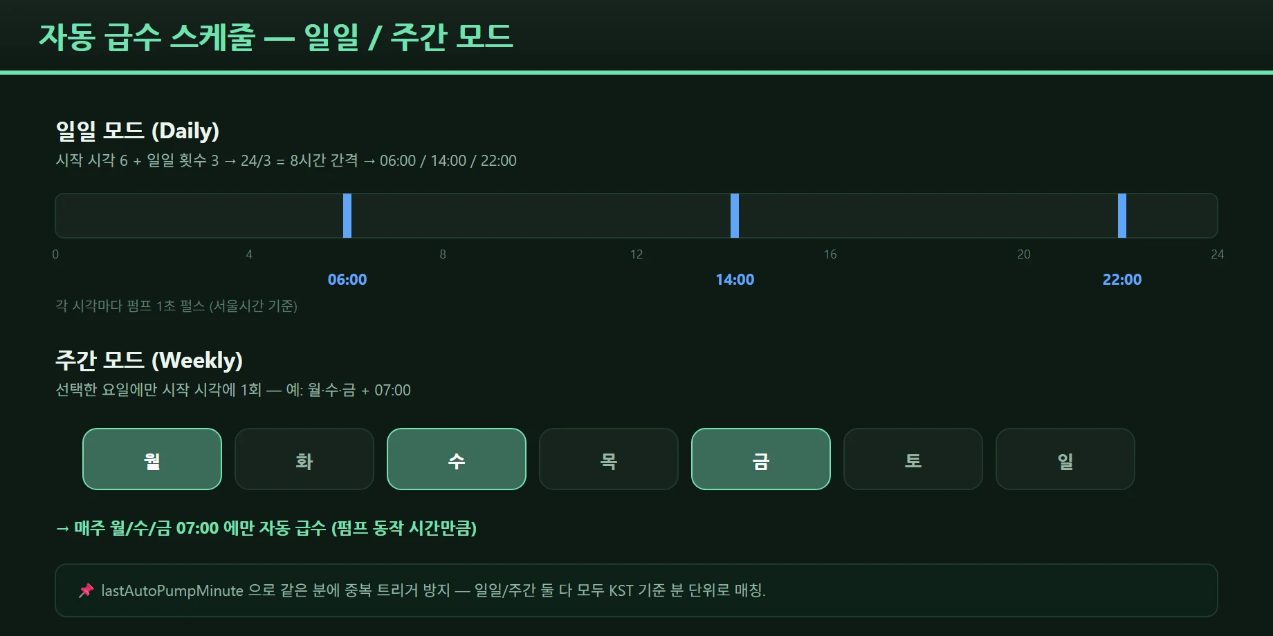
The automatic watering schedule has two modes, daily and weekly.
Daily mode: give it a start time and a number of runs N per day, and it fires every 24/N hours. With 06
and 3 runs, for example, the pump runs for one second at06:00 / 14:00 / 22:00.
Weekly mode: tick the weekdays (Monday through Sunday) and set a start time, and it runs once at that time on the selected days only.
The original design was condition-based — turn the pump on whenever soil moisture fell below a threshold. But a soil probe sitting in air, or one with a disconnected wire, reads 0, and 0 is always below the threshold, which risks running the pump forever. That is why we moved to a time-based schedule.
Troubleshooting 2: the black MJPEG screen
Symptom
ffmpeg pulled JPEGs out of the Tapo RTSP stream and served them as
multipart/x-mixed-replace; boundary=ffmpeg. Some browsers showed a black screen. The ffmpeg process was
alive and the JPEG data was fine.
Hypotheses
A case problem in the boundary string? A missing Content-Length header? An ffmpeg output buffer timing
issue?
The real cause
The multipart boundary format ffmpeg emits differs subtly from RFC 2046, and browsers vary in how much they tolerate. In certain browsers the parser gave up after the first frame and left the black screen up.
The fix
We dropped the MJPEG pipe and switched to plain JPEG polling.
- Node.js keeps ffmpeg’s output as a single latest JPEG in memory
- The browser polls
/camera/snapshotroughly every 120ms by swapping the image source - Leaving the video tab shuts ffmpeg down after 8 seconds idle, so normal CPU use is 0%
It is simpler than MJPEG and compatible everywhere, and the CPU load only appears when it is needed.
Troubleshooting 3: the pump that never auto-stopped, and a Modbus write collision
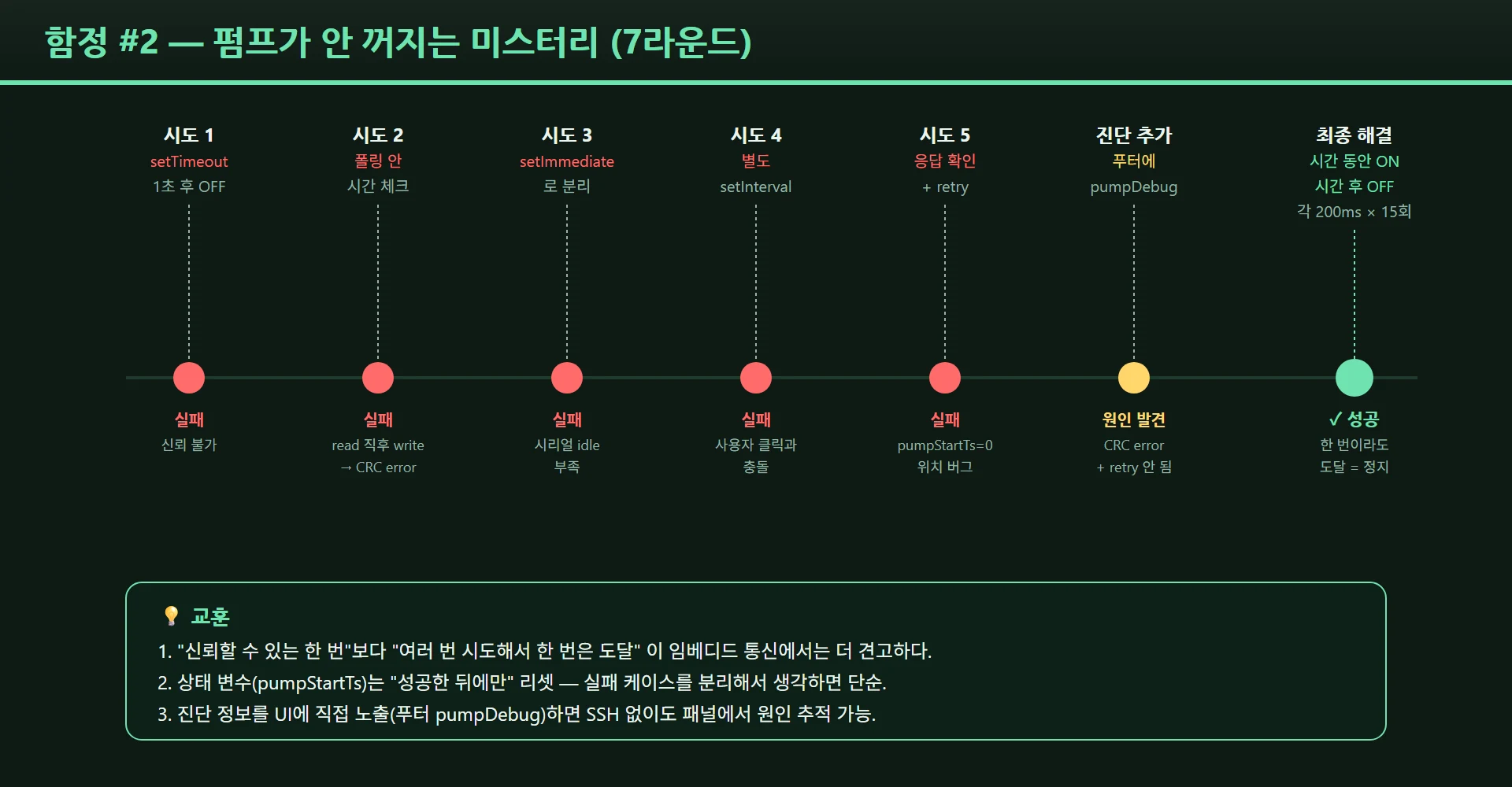
The pump auto-stop problem took the longest of the three.
Symptom
The pump is supposed to run for one second and stop. Pressing “emergency stop” manually in the UI does stop it. But a pump started by the automatic schedule kept running well past its one second.
Attempts and hypotheses
Round 1 — turn it off after one second with setTimeout
setPump(true);
setTimeout(() => setPump(false), 1000);
Sometimes the timeout fired and the pump still did not stop. Strange.
Round 2 — confirm the response, then turn off
Read the coil back after the Modbus write, and retry the OFF if it still reads 1. Still failed occasionally.
Round 3 — a state machine based on pumpStartTs
Record the start time in pumpStartTs and turn off from the polling loop once enough time has elapsed. This
should have been the most robust option, and it still had failures.
Round 4 — add logging and actually debug
The logs showed two problems happening at once.
The real causes
Cause A: colliding Modbus writes
The Node.js Modbus poll sends a holding-register read every 100ms. When the timing of an OFF command overlaps
a poll read, the two collide on the serial bus and the OFF command is lost. At 9600bps, 100ms is tight.
Cause B: pumpStartTs reset too early
// Bug: reset to 0 before the OFF is even sent
pumpStartTs = 0;
await setPump(false);  // no retry if this fails
Clearing pumpStartTs before sending the OFF means a failed send is still treated as “already off”, so
nothing ever retries.
The fix
The way to solve both at once was “keep sending OFF until it is off.”
// Key idea: hold ON for one second, then keep sending OFF every 200ms until it actually stops
// pumpStartTs stays set until the OFF is confirmed
if (pumpRunning && elapsed < PUMP_DURATION) {
  sendCoil(COIL_PUMP, 1);   // hold ON
} else if (pumpRunning) {
  sendCoil(COIL_PUMP, 0);   // keep trying OFF (every 200ms)
  if (confirmedOff) pumpStartTs = 0;  // reset only after confirmation
}
One successful frame is enough to stop it, and even if several are lost, another attempt is guaranteed 200ms later.
The lesson
Pick a conservative serial polling interval from the start — 500ms or more. 100ms is a burden at 9600bps. And hold to the rule that a state flag is reset only after the work has actually completed. Those two mistakes compounded, and that is why the debugging dragged on.
Smaller UI annoyances
Toggle buttons flickering: when SSE delivered a stale value, a button would snap back to its old state
before flipping to the new one. The fix was a pendingTags table that shows the user’s value preferentially
for two seconds after a click, with SSE resyncing afterwards.
The settings modal closing mid-scroll: we had made it close on an outside click, and scrolling a long modal would catch the outside area and dismiss it. Now the settings modal closes only via the X button or “Save and apply”.
Deployment onto Senvas Touch
Deployment onto Senvas Touch has a simple layout.
Smart_Farm_NodeJS/
├── app.js              # HTTP + SSE + Modbus + camera + automation
├── modbus_rtu.js       # zero-dependency Modbus RTU master
├── index.html          # UI built for 1024×600
├── package.json        # no dependencies
├── config.json         # persisted settings (port, crop, schedule, camera)
└── README.md
Upload the ZIP with install_program from the Senvas Touch MCP, set projectType: NodeJs and
executableFileName: app.js, and the install is done. For the camera feature add one line,
sudo apt install -y ffmpeg. Enable autostart and it comes up in Chromium kiosk mode at boot.
Thanks to the zero-dependency rule, deployment finishes in seconds even without an internet connection and
without npm.
Smart farm HMI retrospective
What worked
The zero-dependency rule paid off on site. Embedded devices often sit on flaky networks or none at all.
Being able to upload a ZIP without npm install made deployment radically simple.
Keeping the firmware as a dumb actuator was also the right call. Changing the photoperiod or the number of waterings never means touching the Arduino — you change a value in the settings dialog.
Inline SVG icons mattered more than expected. Emoji render differently across platforms; inline SVG looks identical on every device.
What we would do differently
- Set the serial polling interval to 500ms or more from the beginning. 100ms was too much at 9600bps.
- When choosing a Modbus library, check how it packs bits before anything else, in the docs or the source. This was the single biggest time sink.
- For momentary actions like the pump (one second ON, then OFF), letting the firmware own the timer is a valid alternative. We handled it on the HMI because of the “keep the firmware as simple as possible” rule, but that trade-off should be a deliberate choice.
Ideas for later
- User-defined crop presets (add and edit JSON directly)
- A soil-moisture guard on scheduled watering (skip the run if moisture is already sufficient)
- Video recording with ffmpeg (hourly files)
- Multiple cameras
- External alerts when temperature or humidity crosses a threshold (Telegram, for instance)
This system runs on a Senvas Touch panel and is currently operating in a real smart farm. The code will be published separately.
If you are somewhere between embedded and web and running into similar trouble — especially the Modbus coil bit-packing problem — we hope this post helps a little.
The core of this smart farm HMI is keeping the firmware a dumb actuator and moving all automation, plus zero-dependency deployment, onto the HMI side.
Afterwards: the tomatoes outgrew the case
We left the crop preset on tomato for a while. The photos speak for themselves.
The case was built around the size of a seedling, so once a crop actually grows it runs out of room quickly. Next time, the height of the case is the first thing to reconsider.
Kit used — this project was built with the eduino smart farm kit.
Contact
- Email: [email protected]
- Instagram: https://www.instagram.com/going.sen/
- Website: https://intosen.com/kr/consult/
Comments
Enter a nickname to leave a comment, or sign in with Google or GitHub.