
A two-axis solar tracker that follows the sun with a four-quadrant LDR sensor, wired together from Arduino Mega firmware, a Python backend on a Raspberry Pi and a 7-inch touch HMI — and a record of the communication, jitter and deployment problems we worked through one at a time.
1. What we built with the two-axis solar tracker
The theory behind solar tracking control is common knowledge: a panel that follows the sun produces more power. The problem is that building one drags a surprising number of headaches along behind it.
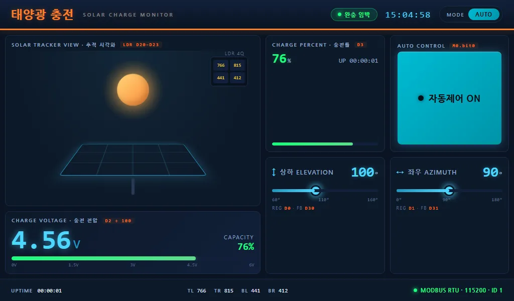
The goal was simple: place four LDRs (light dependent resistors), one per quadrant, to sense the direction of the sun; track the panel angle with two servo axes; and show charging voltage and current live on a 7-inch touch panel. Plus a manual mode where the user can set the angle directly.
The result splits into three layers. The Arduino Mega is the edge controller that reads the sensors and moves the servos. The Raspberry Pi collects data over Modbus RTU and pushes it to the HMI through a web server. The HMI is a single HTML file that comes up as a Chromium kiosk on top of the Senvas Touch launcher.
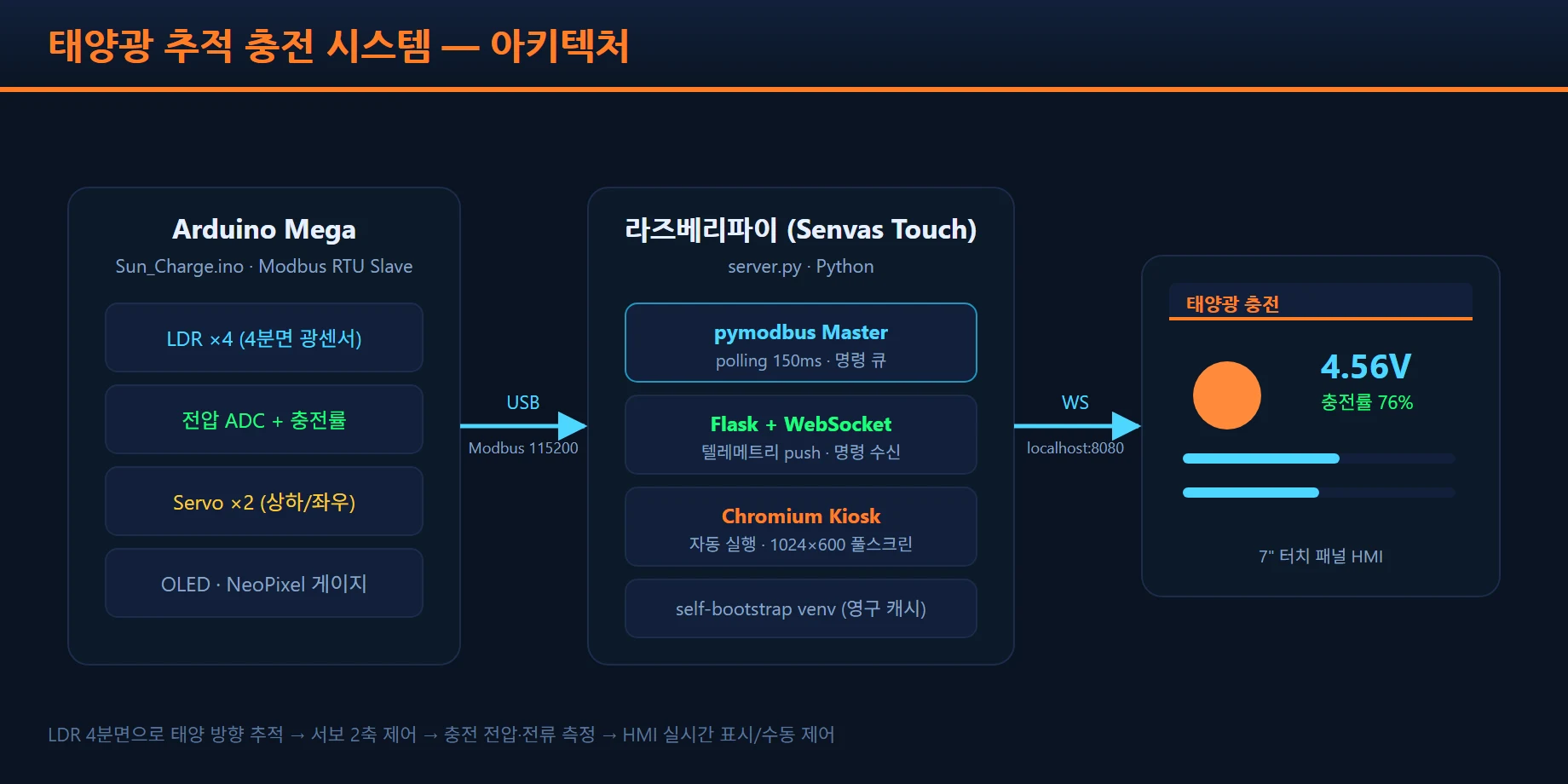
The full data flow:
Sun position → four-quadrant LDR → Arduino drives two servo axes → charge voltage/current measured
            → reported to the Raspberry Pi over Modbus RTU (115200bps)
            → pushed live to the browser HMI over WebSocket (150ms polling)
            → the user adjusts angle manually with the HMI sliders
            → commands go back to the Arduino over Modbus
2. Hardware: four LDR quadrants and two servo axes
There is a reason we used a four-quadrant LDR light sensor for tracking. The common single-LDR-plus-comparator approach cannot tell you whether the current position is the brightest one. A quadrant layout compares adjacent pairs and gives you the direction error as a vector.
- Azimuth error:
(sum of left LDRs - sum of right LDRs) / total sum - Elevation error:
(sum of top LDRs - sum of bottom LDRs) / total sum
Normalizing by ratio means relative direction still works on an overcast day. The ADC is 10-bit, so values run 0–1023, and the servo ranges are limited to the mechanics: 0°–180° for azimuth and 60°–160° for elevation.
One subtle trap: the direction the LDRs point at is not always the position of maximum output. On a cloudy day with strong diffuse light, or when there is a reflection, the LDRs can call the wrong direction “bright”. This project aimed at demonstrating general tracking rather than that level of precision, so we stayed with a pure LDR approach.
3. Three layers: firmware, backend and HMI
Firmware — cooperative multitasking
The most important design decision in the Arduino firmware (424 lines) is that it never calls delay(). A Modbus
RTU slave has no idea when the master will ask for something. If delay() is holding the loop, the response
comes late and the master starts timing out and retrying.
Instead we used millis()-based time slices. Each task runs only when its period is due and returns
immediately.
void loop() {
  rtu.loop();                               // Modbus first, always
  unsigned long now = millis();
  if ((unsigned long)(now - sensor_ts)  >= 30UL)   { sensor_ts  = now; SensorTask();  }
  if ((unsigned long)(now - control_ts) >= 10UL)   { control_ts = now; ControlTask(); }
  if ((unsigned long)(now - display_ts) >= 1000UL) { display_ts = now; DisplayTask(); }
  // unsigned differences → safe across the 49.7-day millis() wrap-around
}
Because rtu.loop() is called first every pass, Modbus responses go out immediately no matter what the
sensor, control and display tasks are doing. Handling timestamps as unsigned long keeps the 49.7-day
wrap-around safe.
For a heartbeat, coil M2 toggles once per second. If the HMI does not see that bit change within a second it declares the link down and turns the status indicator red.
Backend — a single-process server
The Raspberry Pi backend (server.py, 534 lines) does three jobs in one file. It polls as a pymodbus master, it pushes data to the HMI over Flask and WebSocket, and it spawns the Chromium kiosk itself.
def modbus_loop():
    while True:
        # 1) apply UI commands first
        while not command_queue.empty():
            _apply_command(client, command_queue.get_nowait())
        # 2) read all 32 telemetry words in one request
        rr = _mb_call(client.read_holding_registers, address=0, count=32, slave_id=1)
        # 3) push to the browser over WebSocket
        _broadcast()
        time.sleep(0.15)   # 150ms polling
The command queue pattern is the heart of it. Slider moves and button presses from the HMI accumulate in the queue and are flushed together at the start of each polling cycle. That keeps Modbus reads and writes from interleaving, so there are no timing collisions.
HMI — a single HTML file
The HMI (SolarCharge.html, 696 lines) uses no framework. Running React or Vue on a 1024×600 seven-inch panel is heavy, and redeploying it is a chore. Plain HTML, CSS and JavaScript in one file means deployment is nothing more than zipping it and uploading.
If the WebSocket drops, it retries every second, and the connection state is visualized by the Modbus status indicator in the footer. While a slider is being dragged, an 800ms grace period blocks the value jumping from the backend echo.
4. The data contract: the Modbus register map
The Modbus register map defines the contract between the Arduino and the Raspberry Pi. Documenting it makes debugging far easier on both sides.
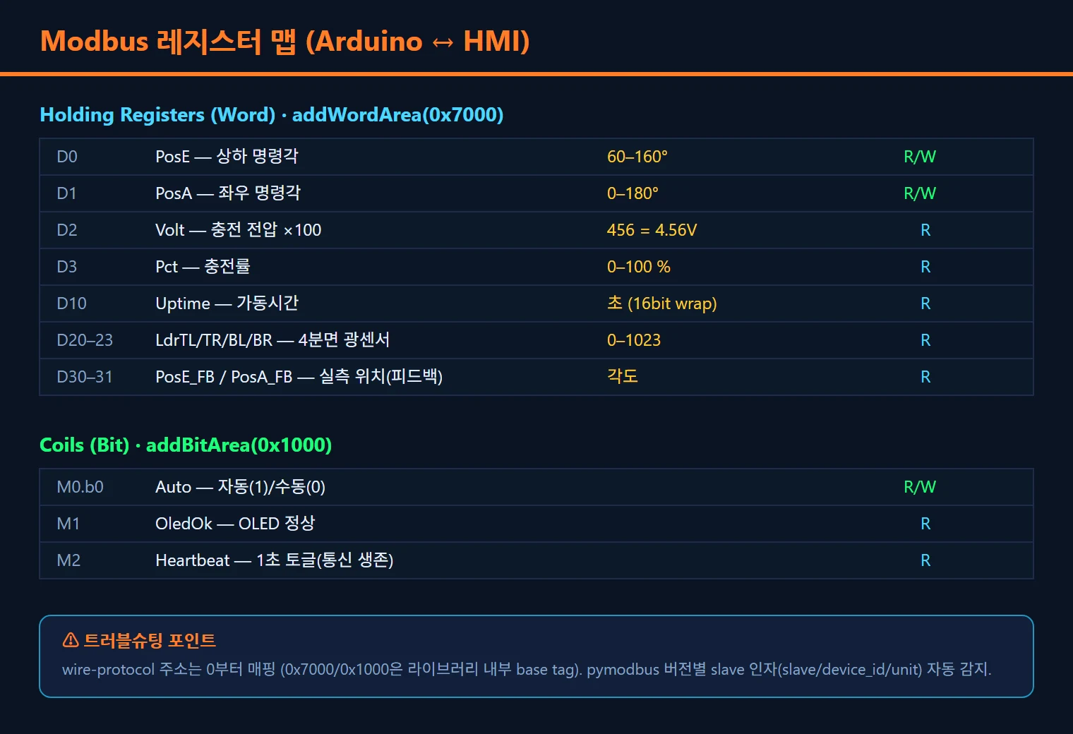
The registers that matter:
- D0–D3: raw four-quadrant LDR values (0–1023)
- D4: charge voltage (×10 scale, so 123 = 12.3V)
- D5: charge current (×100 scale)
- D10: current azimuth servo angle (0–180)
- D11: current elevation servo angle (60–160)
- D20–D21: target angle write registers, HMI to Arduino (manual mode)
- M0: automatic/manual mode bit
- M2: heartbeat bit (toggles every second)
With a register map defined, “why is this value wrong?” becomes “let’s read register D4 directly”. That is far quicker than debugging in the abstract.
5. The fight against servo jitter — a signal processing pipeline
Removing servo jitter is the problem we spent the longest on. Servos that twitch, or suddenly snap to a new position, are something every embedded developer meets eventually.
Symptom
When it first ran, the servos shivered constantly. The LDR values wandered by ±2–3 LSB from ADC noise alone, and that was enough to make the error calculation swing +1, -1, +1, -1 every control cycle, firing repeated commands at the servos.
Hypothesis and the real cause
“Wouldn’t a PID fix this?” was the first thought. But raising the P gain made the oscillation worse, and the D term amplified the noise directly. Solar tracking has an extremely slow disturbance rate — the speed of the sun crossing the sky. It does not need a fast PID response; it needs slow, stable tracking.
The real problem was that the signal itself was dirty.
The fix — three lines of defense
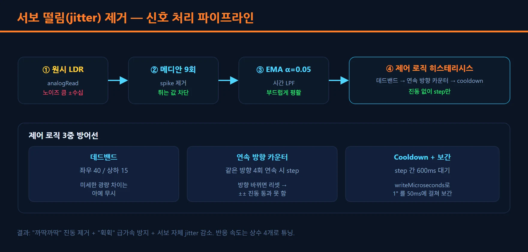
Raw LDR values pass through three stages before they reach the control logic.
Stage 1 — median filter (9 samples): removes impulse noise, the momentary spikes. An averaging filter gets dragged along by outliers; a median takes the middle value and barely notices a spike.
Stage 2 — EMA (exponential moving average, α = 0.05): smooths the remaining high-frequency noise. A smaller α weights history more heavily and gives a smoother result, at the cost of reacting more slowly to real change.
Stage 3 — triple hysteresis in the control logic:
// (1) deadband — ignore small differences (40 azimuth / 15 elevation)
if (abs(azError) > azDeadband) {
  int dir = (azError > 0) ? +1 : -1;
  // (2) direction streak counter — step only after 4 consecutive same-direction reads
  if (sameDirection) azDirStreak += dir; else azDirStreak = dir;
  if (abs(azDirStreak) >= DIR_STREAK_TRIGGER &&
      // (3) cooldown — wait 600ms after a step
      (now - lastAzMove) >= MOVE_COOLDOWN_MS) {
    azPos += dir; azDirStreak = 0; lastAzMove = now;
  }
}
// plus writeMicroseconds interpolation to spread 1° smoothly over 50ms- Deadband: any error at or below the threshold (40 azimuth, 15 elevation) is ignored outright. It accepts small jitter as the accuracy limit of the LDRs.
- Direction streak: the same direction has to arrive four times in a row before the servo actually moves. That filters out the transient noise of a direction flipping for one sample.
- Cooldown: after a move, 600ms must pass before another. It gives the servo time to reach its target and prevents chain reactions.
The servo motion itself is interpolated with writeMicroseconds(), spreading one degree over 50ms, which also
reduces mechanical shock.
Tuning — the response versus stability trade-off
| Constant | Stability first | Balanced (final) | Response first |
|---|---|---|---|
| DIR_STREAK_TRIGGER | 6 | 4 | 2 |
| MOVE_COOLDOWN_MS | 700 | 600 | 250 |
| Deadband (azimuth/elevation) | 60/25 | 40/15 | 30/10 |
| EMA α | 0.05 | 0.05 | 0.15 |
Push any one constant to an extreme and another problem appears. Cutting the cooldown to 250ms produced a new symptom of sudden lurching acceleration. Lowering the streak to 2 made it far too sensitive to scattered light on cloudy days. In the end all four constants had to be tuned together.
Do not paper over embedded jitter with a PID. Grind it out at the signal stage.
6. Seven rounds of deployment troubleshooting
On-site deployment troubleshooting is probably the most relatable section. The gap between “code that works” and “code that runs on the actual device” is always wider than expected.
Round 1 — “the program runs but the screen is blank”
Symptom: backend logs normal, seven-inch panel black.
Cause: Senvas Touch will run a Python process for you, but it has no way of knowing what GUI that process intends to open. Something had to launch the Chromium kiosk.
Fix: server.py now spawns Chromium in kiosk mode from a background thread once the HTTP server is ready.
Lesson: never assume “the framework handles it”. Check what the runtime environment actually expects.
Round 2 — “ModuleNotFoundError: flask_sock”
Symptom: immediate crash on first run.
Cause: it ran under the system Python, which did not have the packages installed by pip.
Fix: a self-bootstrap block at the top of server.py. If there is no venv it creates one, installs the
dependencies, and re-executes itself with os.execve(). Every run after that happens inside the venv.
Lesson: do not assume anything about the Python state of the target machine. Code that builds its own environment is the safest kind.
Round 3 — “Modbus does not answer (No response after 3 retries)”
Symptom: repeated timeout errors in the backend log.
We eliminated two candidate causes in turn.
The first: pymodbus changed its API in 3.7 and later, renaming the slave= argument to device_id=. The old
name was simply ignored, so requests went out with the default slave ID of 0. The Arduino was set to ID 1, so
nothing answered. A wrapper function that detects the argument name per version fixed it.
The second: we confirmed from the logs that the base address was 0, not 0x7000. That turned out not to be a
problem.
Lesson: library version incompatibility fails “quietly, with the wrong value”. There was no warning that
slave=1 was being ignored. You only see it by reading the logs carefully.
Round 4 — “WebSocket: Cannot obtain socket from WSGI environment”
Symptom: a server error the moment a WebSocket connection is attempted.
Cause: waitress is an excellent production WSGI server, and it does not support WebSocket.
Fix: switched to Flask’s built-in threaded development server. For a single panel with a handful of connections, the built-in server is plenty.
Lesson: know the limits of your tools. We picked waitress because it was “more stable”, but stability means nothing if it does not support the feature you need.
Round 5 — “the data does not move”
Symptom: values appear on the HMI but never change.
Cause: the USB-serial adapter port did not match the Arduino serial port number, and the 115200 baud rate needed rechecking on both sides.
Fix: recheck the physical wiring and confirm the same baud rate at both ends.
Lesson: check the hardware wiring before you start debugging software.
Round 6 — “the servos are twitching”
Covered in detail in section 5. This round took the most time, and the three lines of defense solved it.
Round 7 — “startup takes too long / the slider value jumps / the thumb is misaligned”
Three small problems landed in one round.
Startup time, 60 seconds to 5: the venv is now cached permanently in the home folder instead of being recreated every time. It survives a reinstall.
Slider values jumping: moving a slider makes the backend take the command, write the register, and echo the
value back to the HMI on the next poll. That echo overwrote the value while the user was still dragging, so it
looked like a jump. We added an 800ms grace period after pointerup so echoes are ignored while the control is
in use.
CSS thumb alignment: non-standard WebKit behavior left the slider thumb offset from the track. Replacing it
with the standard pattern (6px track with margin-top: -8px) fixed it.
7. Solar tracking control recap — what we learned and what is left
Pulling together what building this solar tracking control confirmed:
On architecture: the cleaner the separation of roles, the easier the debugging. We could verify independently whether the Arduino, Modbus, the backend or the HMI was at fault. With the register map acting as a contract, narrowing down which layer had the problem was fast.
On signal processing: ADC noise is larger and more varied than you expect. Spikes needed a median, Gaussian noise needed an EMA, and boundary oscillation needed hysteresis — three different tools for three different problems. There was no single filter that solved everything.
On deployment: the self-bootstrap pattern, where the code guarantees its own runtime environment, is powerful for embedded and IoT deployment. Turning “install then run” into “run and it prepares itself” cuts a lot of operational load.
This project runs on the Senvas Touch industrial touch launcher. Because deployment is nothing more than uploading one ZIP and naming the executable, swapping just the HMI screens or just the backend logic without touching the firmware is very quick.
A few tasks remain. Today the tracker follows the brightest direction the LDRs see, but the true maximum power position has to be found with voltage hill-climbing MPPT (Maximum Power Point Tracking). LDR tracking also becomes unstable under clouds or indoor scattered light. And at night it needs return logic that holds the last angle from sunset and then swings back to the sunrise position.
This was a development log focused less on technical completeness and more on how we solved the problems we actually met. We hope it works as a record of “here are the traps” for someone starting their first embedded project.
The core of a two-axis solar tracker is splitting the layers with a register map so faults can be isolated, and grinding servo jitter out in the signal processing stage rather than covering it with PID.
The full code is Sun_Charge.ino (firmware), server.py (backend) and SolarCharge.html (HMI), packaged as a Senvas Touch deployment bundle (SolarCharge.zip) that uploads straight onto the touch panel.
Kit used — this project was built with the eduino solar tracker kit.
Contact
- Email: [email protected]
- Instagram: https://www.instagram.com/going.sen/
- Website: https://intosen.com/kr/consult/
Comments
Enter a nickname to leave a comment, or sign in with Google or GitHub.