
We drew how DV-HMI builds a program, and how that program runs on a panel, as a small office and factory. The scene below is not a video. It runs right here on this page. Click a person or a machine to see which real part it stands for and what it does.
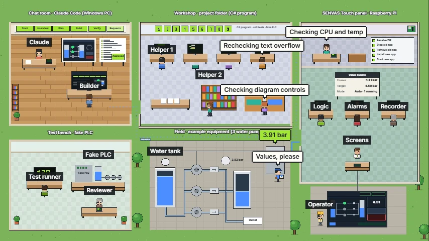
The scene is an example based on our three-pump water supply sample and is not connected to real equipment. Most of the people stand for parts of the program, and they move more slowly than the real thing so you can follow along.
How to use the scene
- Step buttons: the eight buttons at the bottom jump straight to a step
- People and machines: click one to open a card with its real name and what it does
- Top right buttons: pause, name tags on or off, full view, zoom in and out
- Drag: drag the scene to move around. On a phone, dragging up or down scrolls the post
What the five areas really are
| Area | What it really is |
|---|---|
| Chat room | The Claude desktop app (Code tab), the DV-HMI plugin and the dashboard |
| Workshop | The project folder: helper agents, the git repository, HMI knowledge documents and the Devinno libraries |
| Test bench | Builds and unit tests, a reviewer who did not write the code, and a device simulator (fake PLC) |
| Field | Example equipment: a water tank, three pumps, a pressure tank and a Modbus TCP PLC |
| Panel | The launcher on a Senvas Touch (Raspberry Pi) and the C# app built with DV-HMI |
Steps 1 to 5: building the program and putting it on the panel
1. Three questions. Say what you want to build, and Claude asks only for a name, a way of working and a target (Windows PC or Senvas Touch), then prepares the project. A dashboard opens alongside.
2. Screen draft. While you talk, Claude draws a screen draft and writes the requirements. A person looks them over, says what to change, and approves them to lock them in.
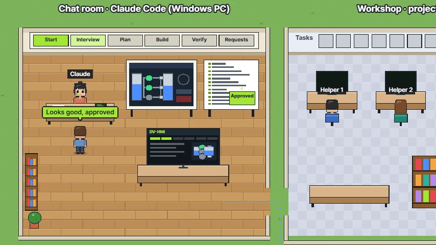
3. Plan and build. The requirements are split into small work items, nine in the sample. Helper agents build items that do not overlap at the same time, and each item must pass the build and tests to count as done.
4. Verify. All tests run, and a reviewer who did not write the code takes another look. AI testing only ever touches the fake PLC. Running the program and testing on real equipment are done by a person.
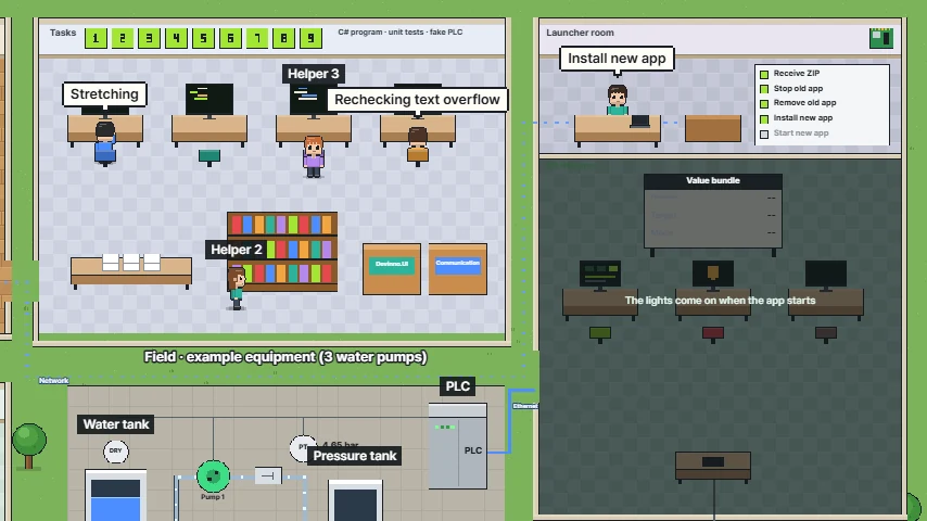
5. Panel deployment. The deploy button on the dashboard bundles the program and sends it to the panel. The launcher stops the old app, installs the new one and starts it. The sample’s record shows 7.3 MB uploaded in 8 seconds.
Steps 6 to 8: the program running on the panel
6. Values to screen. The comms worker receives PLC values and swaps in the whole value bundle at once. The logic worker runs comms status, alarms and logging on each cycle and refreshes the screen. In the sample, comms runs every 0.2 seconds and logic every 0.5 seconds.
7. Press and it goes to the PLC. When a button is pressed, the logic worker first checks whether it is allowed. If locked, the reason is shown. If allowed, the comms worker carries the command to the PLC. Running a pump takes a one-second long press.
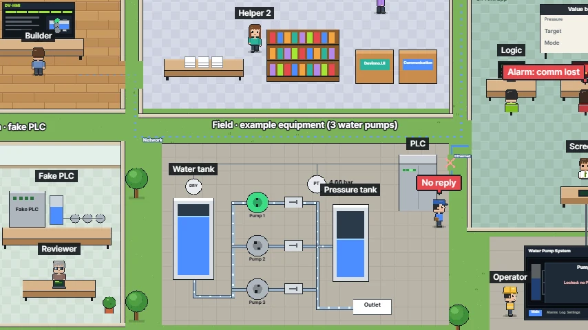
8. Comm loss. When replies stop, values are cleared to -- and only the stop-all button remains. Alarms are not judged on stale values, and the pressure log keeps a gap so the graph line is not joined across it.
Summary
- In steps 1 to 5, a person speaks and approves, and the tools confirm completion with builds and tests
- In steps 6 to 8, the app runs with comms, logic, alarms, logging and screens each doing their own part
- For what works today and real screens from the sample, see DV-HMI Features and a Water Pump Sample
If a part of this flow was hard to picture from text alone, press that step’s button.
Contact
- Email: [email protected]
- Instagram: https://www.instagram.com/going.sen/
- Website: https://intosen.com/kr/consult/
Comments
Enter a nickname to leave a comment, or sign in with Google or GitHub.