
This is a popping machine controller running on a custom RP2040 board, programmed with Senbrino. It cycles five solenoids and a motor through a fixed sequence and takes its process timing from dials on the operator panel.
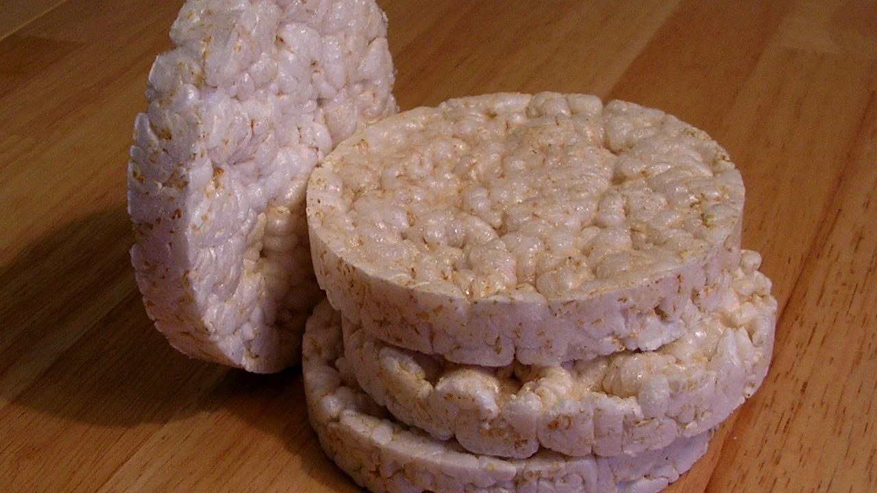
What a popping machine does
Rice or corn goes between two heated mold plates. The machine squeezes it under pressure, then snaps the mold open. The moisture inside flashes to steam and the grain puffs into a thin, crisp cake. The round rice cakes you see in stores are made this way.
Every cake takes the same routine: close the mold, press, open, eject, feed the next charge. The order and the timing are the controller’s job.
Project overview
| Item | Detail |
|---|---|
| Customer | Shinyoung ○○○○ |
| Product | Senbrino |
| Hardware | Custom RP2040-based control board |
| Functions | Automatic sequence · manual operation · emergency stop with restart lockout · solenoid interlocks · dial-based timing |
Hardware: custom RP2040 board
The board is the customer’s own design. We registered it in Senbrino as a board package.
| Block | Role |
|---|---|
| 11 digital inputs | Sensors, switches on the inner and outer operator panels, emergency stop |
| 10 digital outputs | Five solenoids, motor, buzzer, indicators |
| 8 analog inputs | Operator-panel dials read through a multiplexer |
The board package driver handles input debouncing and the multiplexer channel switching and sampling. The ladder only ever sees settled inputs and dial values.
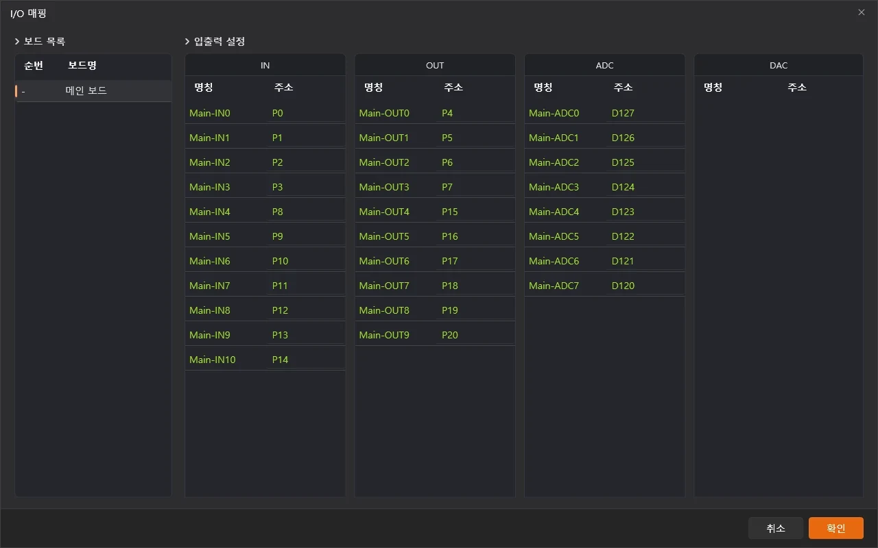
Input, output, and analog slots registered through the board package. Inputs with inverted contact polarity are flagged as inverted in the pin definition.
What the controller does
Automatic mode. Flip the auto switch and the mold, ejector, and feed motor run through their sequence and loop back to the start. Sensors and timers decide when each step ends.
Manual mode. With auto off, the manual switches drive the solenoids directly.
Panels and dials. There are two operator panels, inner and outer. The controller picks whichever one has live dials. The dial values become the hold times and pulse times of the process steps.
Safety. On an emergency input the hazardous outputs drop immediately and the safe-direction outputs hold for a set time. Releasing the emergency does not restart anything. The auto switch has to be cycled off and on first.
How it is built in Senbrino
Ladder for control, C++ for arithmetic
| Role | Where |
|---|---|
| Automatic sequence and safe stop | Ladder state machine, one M bit per step |
| Solenoid interlocks | Ladder: opposite coil’s NC contact plus a changeover delay timer |
| Manual mode, panel selection | Ladder |
| Converting dial values to time | One user function in C++ |
The ladder has four regions. Reading top to bottom: common signals, sequence, output commands, physical coils.
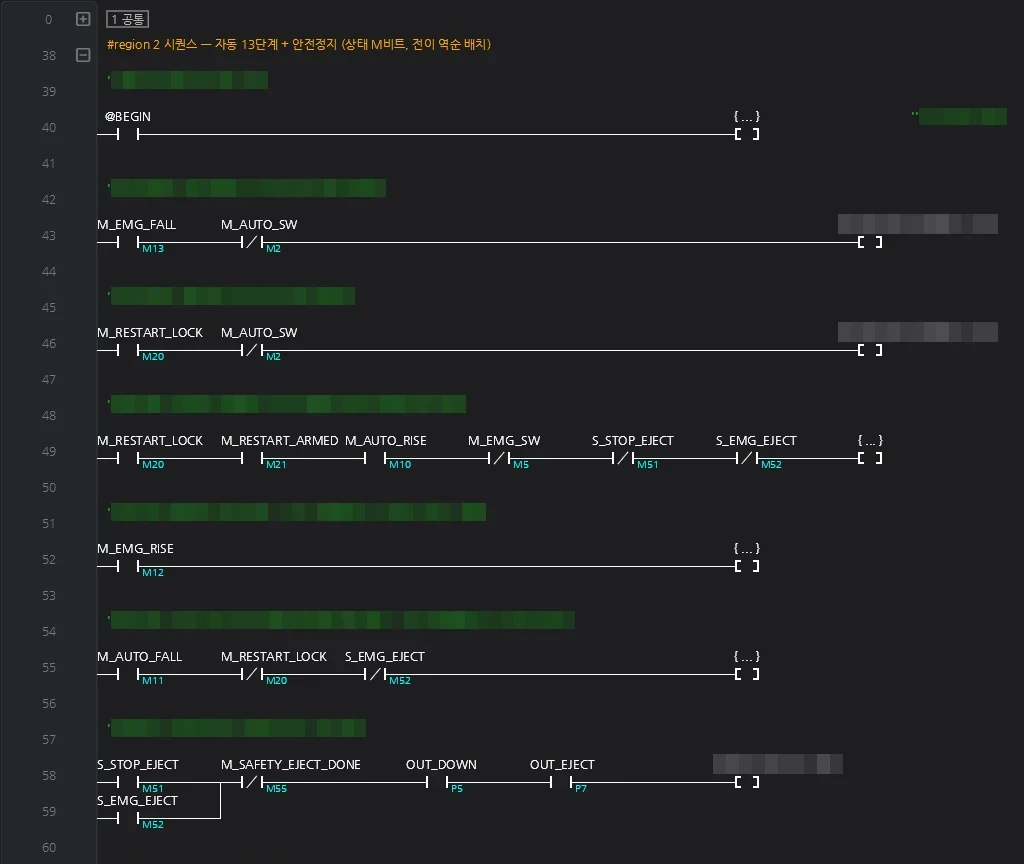
Transition rungs of the sequence region. The emergency transition sits at the top; below it the step transitions are laid out in reverse order so only one step can advance per scan.
Outputs are written in exactly one place
The solenoid coils live only in the output region at the bottom of the ladder. The automatic sequence and the manual mode never touch a coil. They raise command bits, and the output region turns those into coils after passing the interlocks and the emergency guard.
Solenoids that move in opposite directions are paired. When a command drops, its coil drops at once. A coil can only come on after the opposite coil has been off for the changeover delay.
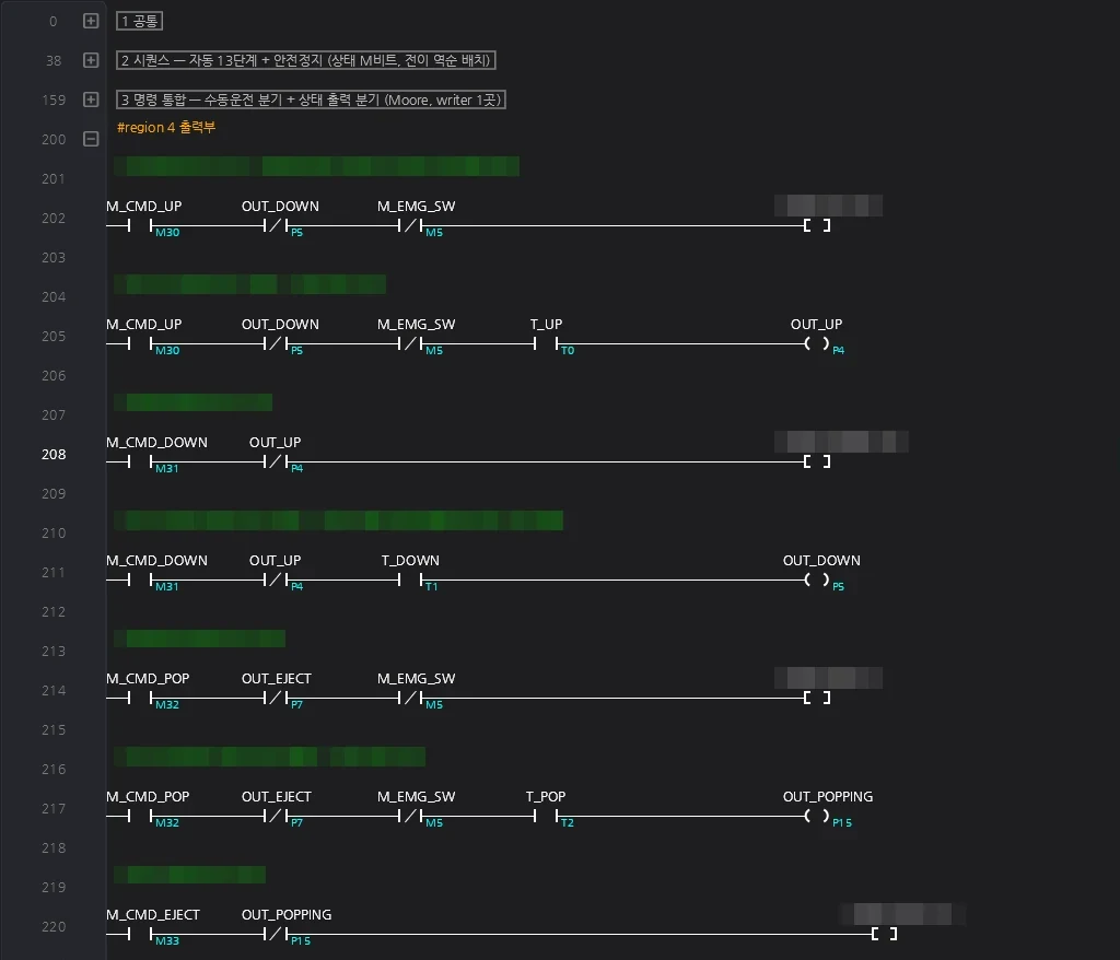
Coil rung of an interlock pair. The opposite coil’s NC contact, the emergency NC contact, and the changeover timer contact are in series.
Dial values become timer presets
A C++ function scales each dial reading into timer ticks and stores it in a D word. The ladder timers take that word directly as their preset, so turning a dial changes the timing from the next step onward.
How the project ran
We used Senbrino’s AI mode.
Interview → Design → Plan → Implement → Verify
The design document and the implementation plan both need a human to read and approve them before the next phase starts. The final verification was done by a separate reviewer who had not touched the implementation. It checked the design’s state transitions, output table, and safety guard table against the ladder item by item.
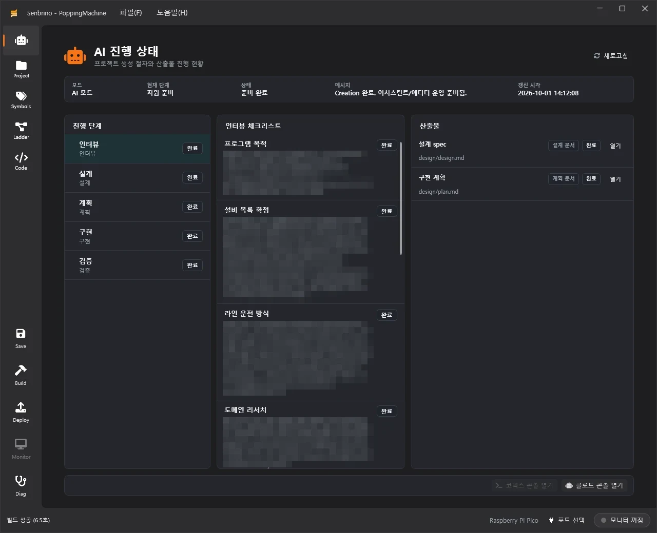
Senbrino’s AI progress screen. Checklist contents are blurred.
Issues along the way
| Issue | Fix |
|---|---|
| With more than 255 monitored cells, the monitor showed values in the wrong cells | Senbrino 0.9.4 raised the monitor slot limit |
| Interlock delays made step timers start before the output actually came on | Put the real coil contact in series with each step timer so it counts from the moment the output is on |
The 255-cell monitor limit
This ladder has more than 255 monitored cells. The Senbrino firmware’s monitor table only held 255, so the build passed with a warning while the editor monitor showed some values in the wrong cells. Control was unaffected. Senbrino 0.9.4 widened the table size and index to 16 bits.
Counting from when the output is really on
Because of the interlocks, the scan that raises a command and the scan where the coil comes on are not the same. A step timer that starts at the command would lose the delay, so the timers are gated on the actual coil contact instead.
Contact
- Email : [email protected]
- Insta : https://www.instagram.com/going.sen/
- Website : https://intosen.com/kr/consult/
We’d be glad to look at your controller project, food machinery or otherwise.
Comments
Enter a nickname to leave a comment, or sign in with Google or GitHub.