
GO Modular IO is a control system that stands on a DIN rail and grows as far as you need. One main board takes relay, analog input and analog output modules beside it, and when you run out of channels you add another of the same module.
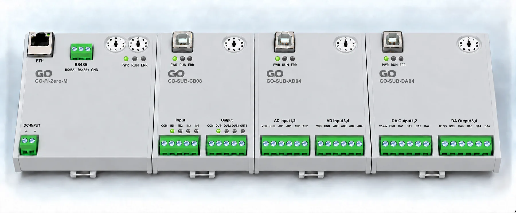
With the covers on. From the left: main, relay and contact input, analog input, analog output, standing side by side on the rail. The front carries the terminal markings, status LEDs and the address switch.
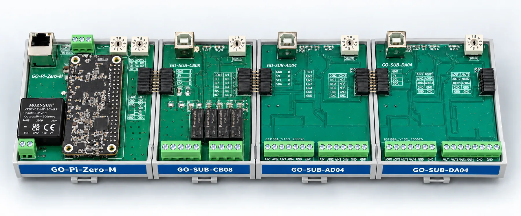
With the covers off. The rest of this post describes what is inside.
Why not put it all on one board
Because every site needs something different.
One machine uses mostly inputs. Another needs four analog channels and no relays at all. Put everything on one board and you buy circuits you never use, and being one channel short means redesigning the whole thing.
Split into modules, you buy what you need and add another when you run short. The price is that the interface between modules has to be defined precisely. That definition is the entire system.
Every board is 81.5 mm tall
| Module | Size | Layers |
|---|---|---|
| GO-Pi-Zero-M | 75.0 × 81.5 mm | 4 |
| GO-SUB-CB08 | 51.0 × 81.5 mm | 4 |
| GO-SUB-AD04 | 51.0 × 81.5 mm | 4 |
| GO-SUB-DA04 | 51.0 × 81.5 mm | 4 |
Only the width changes. Boards at different heights on one rail are not a system, they are a pile of boards. A fixed height means one enclosure height and front labels on the same line.
This is not new. Laying out the boards built in the same family gives:
51×81 · 75×81 · 91×81 · 106×81 · 125×81 · 180×8181 mm tall is fixed and only the width grows with the function. Designing a new module means the height is never a question.
Sixteen wires between modules
The module bus is the interface. One 16-pin connector carries power and communication together.
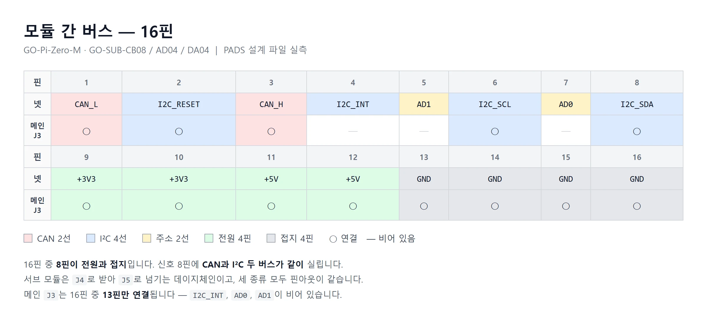
| Group | Pins | Signals |
|---|---|---|
| CAN | 2 | CAN_H · CAN_L |
| I2C | 4 | SCL · SDA · RESET · INT |
| Address | 2 | AD0 · AD1 |
| Power | 4 | +3V3 ×2 · +5V ×2 |
| Ground | 4 | GND ×4 |
Eight of the sixteen pins are power and ground. Half the connector goes to power because the voltage drops toward the far end as modules are added, and the module at the end of the rail has to see the same supply.
On the signal side there are two buses, CAN and I2C. Control data travels on CAN; I2C is spare capacity for attaching something simple later.
The wiring is the same however many you add
Sub-modules have two connectors. J4 receives and J5 passes on to the next module.
Both have the same pin assignment, and all three sub-module types are identical.
So the wiring does not change with the number of boards on the rail. They can be reordered, and one can be removed from the middle.
Each module sets its address on a rotary switch. Fit two of the same module and you just turn the dials differently. No laptop, no configuration software.
What each module does
| Module | Role |
|---|---|
| GO-Pi-Zero-M | Ethernet, CAN and RS-485; carries the compute module. Links to the system above |
| GO-SUB-CB08 | 4 relay outputs + 4 isolated contact inputs |
| GO-SUB-AD04 | 4 analog inputs, 16-bit |
| GO-SUB-DA04 | 4 analog outputs |
The three sub-modules each have their own MCU. The main board does not read values out of them; each measures, decides and puts data on CAN. A busy main board does not disturb the analog sampling interval.
What this series covers
- Part 1 — this post. The system, the 81.5 mm standard, the 16-pin module bus
- Part 2 — the main module
GO-Pi-Zero-M: three buses and the isolation design - Part 3 — the three sub-modules: shared structure and each function block
- Part 4 — full specifications and how to expand
🔧 GO Modular IO series: Part 1 — the system · Part 2 — the main module · Part 3 — the three sub-modules · Part 4 — specs and expansion
Contact
- Email: [email protected]
- Instagram: https://www.instagram.com/going.sen/
- Website: https://intosen.com/kr/consult/
Comments
Enter a nickname to leave a comment, or sign in with Google or GitHub.