
The first three posts covered the system and each module. This one collects the specifications and covers expansion.
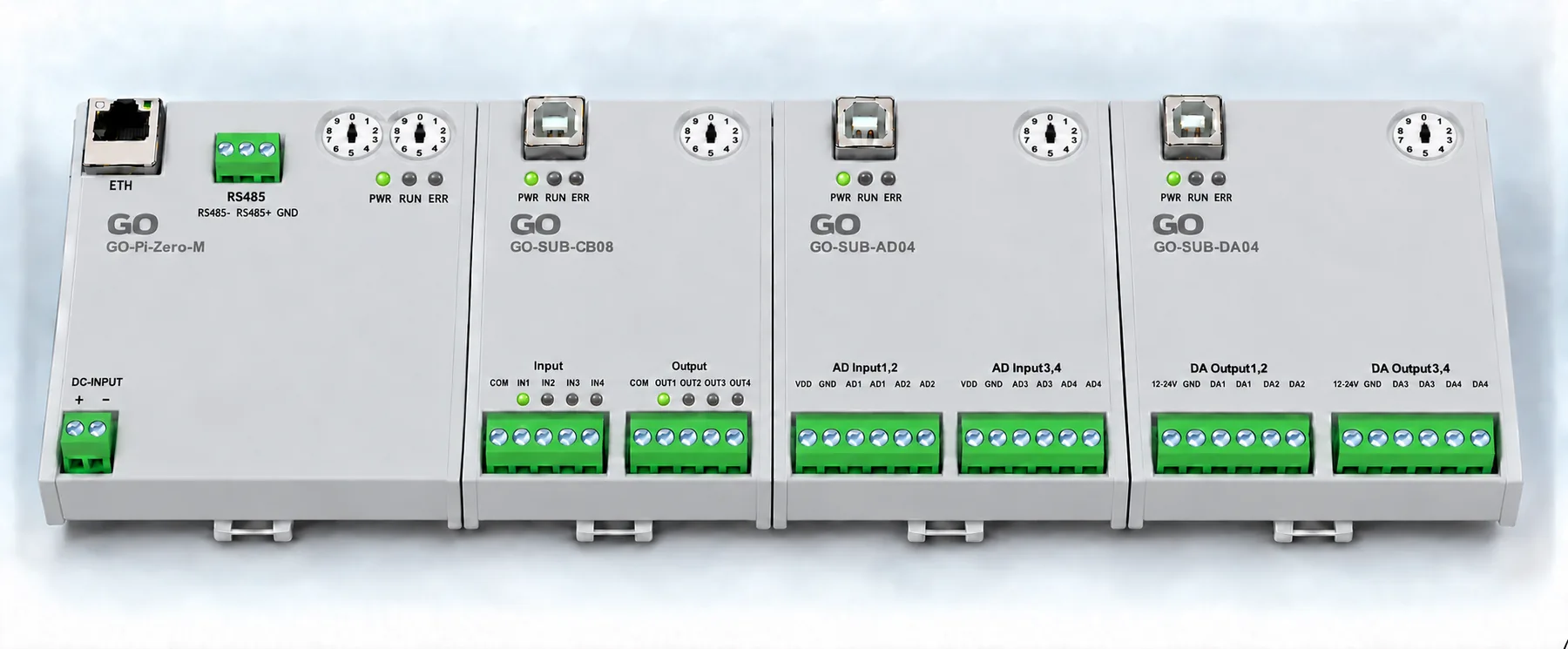
The finished form: covers fitted, mounted on the rail.
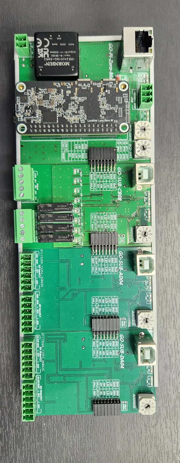
The same units with the covers off - the four boards as actually manufactured and populated.
Full specifications
| GO-Pi-Zero-M | GO-SUB-CB08 | GO-SUB-AD04 | GO-SUB-DA04 | |
|---|---|---|---|---|
| Role | main, comms | relay, contacts | analog input | analog output |
| Size | 75.0 × 81.5 | 51.0 × 81.5 | 51.0 × 81.5 | 51.0 × 81.5 |
| Layers | 4 | 4 | 4 | 4 |
| Parts | 170 | 162 | 121 | 135 |
| Nets | 116 | 112 | 91 | 95 |
| MCU | compute module | RP2040 | RP2040 | RP2040 |
| Channels | — | 4 out + 4 in | 4 in (16-bit) | 4 out |
| Terminals | 2-pin power, 3-pin RS-485 | 5-pin ×2 | 6-pin ×2 | 6-pin ×2 |
| Address | rotary ×2 | rotary ×1 | rotary ×1 | rotary ×1 |
Common to all:
- 81.5 mm tall, four-layer
- 16-pin module bus (CAN 2 · I2C 4 · address 2 · power 4 · ground 4)
- 24 V input, isolated at the main board and distributed as
+5Vand+3V3 - Sub-modules take firmware over USB individually
How many can be chained
The connector is not the limit. The J4/J5 daisy chain continues indefinitely. Two other things set the real limit.
First, CAN bus loading. More nodes means revisiting termination and bus length. The wiring is short inside one enclosure, but the polling interval matters more as nodes are added.
Second, the 5 V current budget. The isolated DC-DC on the main board supplies 5 V at 1.2 A. How many modules fit depends on what each draws, calculated for the worst case where all relays energise at once.
If that runs out, feed power again partway along the rail, or fit a higher-rated isolated module — the same footprint is available at other ratings.
Designing a new module
Three rules are enough to fit an existing system.
- 81.5 mm tall. The width follows the function
- Keep the 16-pin bus. Same pin assignment, same receive-on-J4 pass-on-J5 arrangement
- Fit an address switch. Several of the same module must be able to coexist
The MCU and CAN section can be taken straight from an existing sub-module. All three already share it, and only the function block differs.
Checking the boards against the design
We compared the silkscreen on the manufactured boards against the net names in the design files.
Board silkscreen   CAN_H  CAN_L  SCL  SDA  RESET  3.3V  +5V  ADDRESS
Design file        CAN_H  CAN_L  O_I2C_SCL  O_I2C_SDA  O_I2C_RESET  +3V3  +5V  BCD
The bus signals and power labels match the design. The parts are fitted as drawn — the main
board’s isolated supply is the VRB2405YMD-6WR3 at 5 V 1.2 A, and CB08 has its four relays
in place.
Summary
Three things are fixed in this system — 81.5 mm tall, the 16-pin bus, and an MCU on every module. Everything else follows the function.
Run short of channels and you add a module; need a function that does not exist and you build one to those three rules. Never having to redesign the system from scratch is why it was split into modules.
🔧 GO Modular IO series: Part 1 — the system · Part 2 — the main module · Part 3 — the three sub-modules · Part 4 — specs and expansion
Contact
- Email: [email protected]
- Instagram: https://www.instagram.com/going.sen/
- Website: https://intosen.com/kr/consult/
Comments
Enter a nickname to leave a comment, or sign in with Google or GitHub.