
GO-RP2040-CB08 is an RP2040 I/O board with four digital inputs, four relay outputs, analog I/O and expansion connectors.
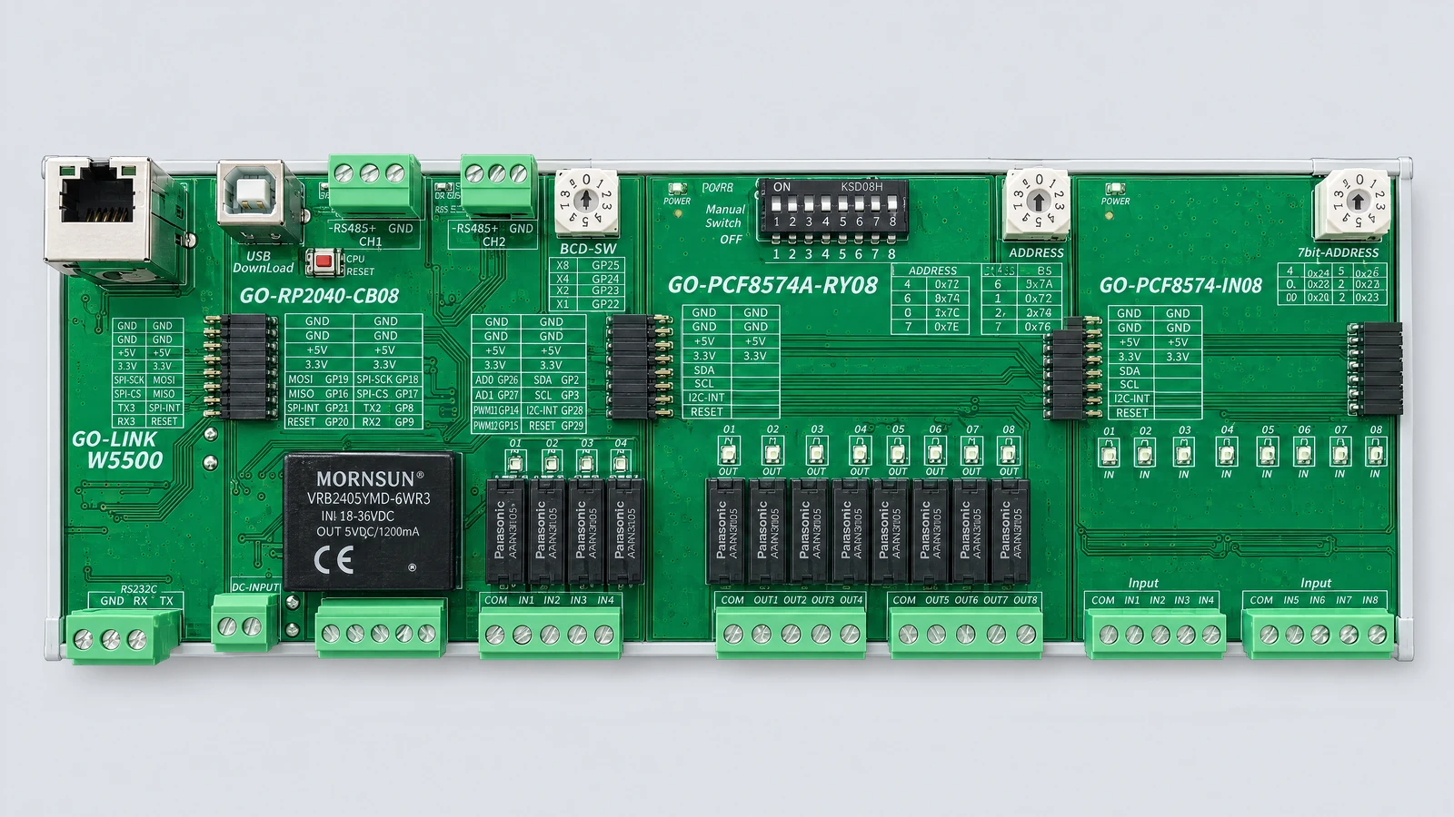
The photo shows the main board connected to a GO-LINK W5500, an eight-point relay output board and an eight-point digital input board.
Specifications
| Item | Specification |
|---|---|
| Model | GO-RP2040-CB08 |
| CPU | RP2040 |
| Digital inputs | 4 points |
| Digital outputs | 4 relay contacts |
| Analog inputs | 2 channels |
| Analog outputs | 2 channels |
| USB | Type-B, program download |
| Serial | RS-485 terminals CH1 and CH2 |
| Ethernet expansion | GO-LINK W5500 |
| Expansion interfaces | SPI, I²C |
| Address setting | BCD rotary switch |
| Buttons | CPU RESET, BOOT MODE |
Main board pin map
| Function | Channel or signal | GPIO |
|---|---|---|
| Digital input | IN1 | GP4 |
| Digital input | IN2 | GP5 |
| Digital input | IN3 | GP6 |
| Digital input | IN4 | GP7 |
| Relay output | OUT1 | GP10 |
| Relay output | OUT2 | GP11 |
| Relay output | OUT3 | GP12 |
| Relay output | OUT4 | GP13 |
| Analog input | AD0 / ADC1 | GP26 |
| Analog input | AD1 / ADC2 | GP27 |
| Analog output | DA0 / DAC1 | GP14 |
| Analog output | DA1 / DAC2 | GP15 |
| CH1 | TX | GP0 |
| CH1 | RX | GP1 |
| CH2 | TX | GP8 |
| CH2 | RX | GP9 |
| BCD switch | X1 | GP22 |
| BCD switch | X2 | GP23 |
| BCD switch | X4 | GP24 |
| BCD switch | X8 | GP25 |
AD0 and AD1 are board labels; ADC1 and ADC2 are their Senbrino channel names. The driver uses PWM signals to drive DA0 and DA1. GPIO numbers do not specify terminal voltage ratings or physical connector pin numbers.
Expansion boards
| Model | Function |
|---|---|
| GO-LINK W5500 | Ethernet |
| GO-PCF8574A-RY08 | 8 relay outputs |
| GO-PCF8574-IN08 | 8 digital inputs |
Related software
See the Senbrino supported board list for the development environment and usage information.
Comments
Enter a nickname to leave a comment, or sign in with Google or GitHub.