
Senbrino is a ladder development environment that lets you use Arduino-compatible boards like a PLC. Write your program in ladder (LD) — the language PLC engineers already know — and Senbrino generates Arduino C++ code, compiles it, and uploads it to the board.
Some jobs are too small to justify a dedicated PLC, yet plain Arduino feels risky once someone has to maintain it on site. This post covers how Senbrino fills that gap.
Draw ladder, get Arduino code
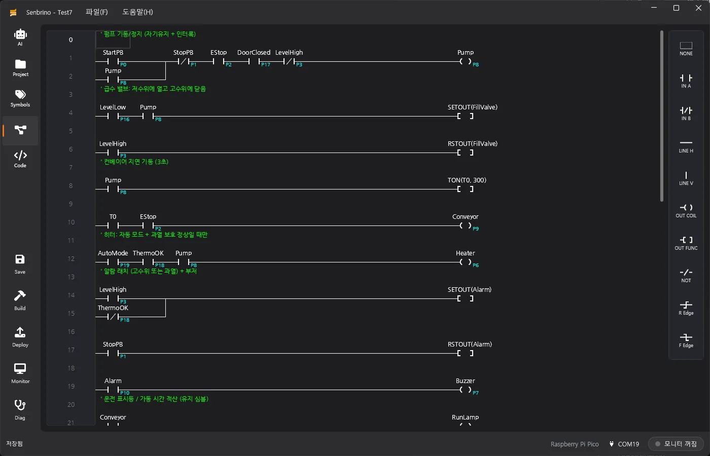
You place contacts, coils, functions (TON, TOFF, CTU, CTD, SETOUT, RSTOUT, MCS and more), parallel branches and edge detection with the keyboard and mouse. Anyone who has worked with a PLC before has almost nothing new to learn.
A static linter runs on every save. It catches duplicate coils, broken rungs, latches that never release, counters with no reset, undefined names and out-of-range setpoints — the kind of thing that is painful to discover on site — while the program is still being edited.
flowchart LR
    Ladder["Ladder editor"] --> Gen["Code generation — Ladder.ino · Symbols.h"]
    Gen --> Build["arduino-cli compile · upload"]
    Build --> Board["Board"]
    Board -. same serial link .-> Monitor["Live monitoring · diagnostics"]
Names instead of addresses
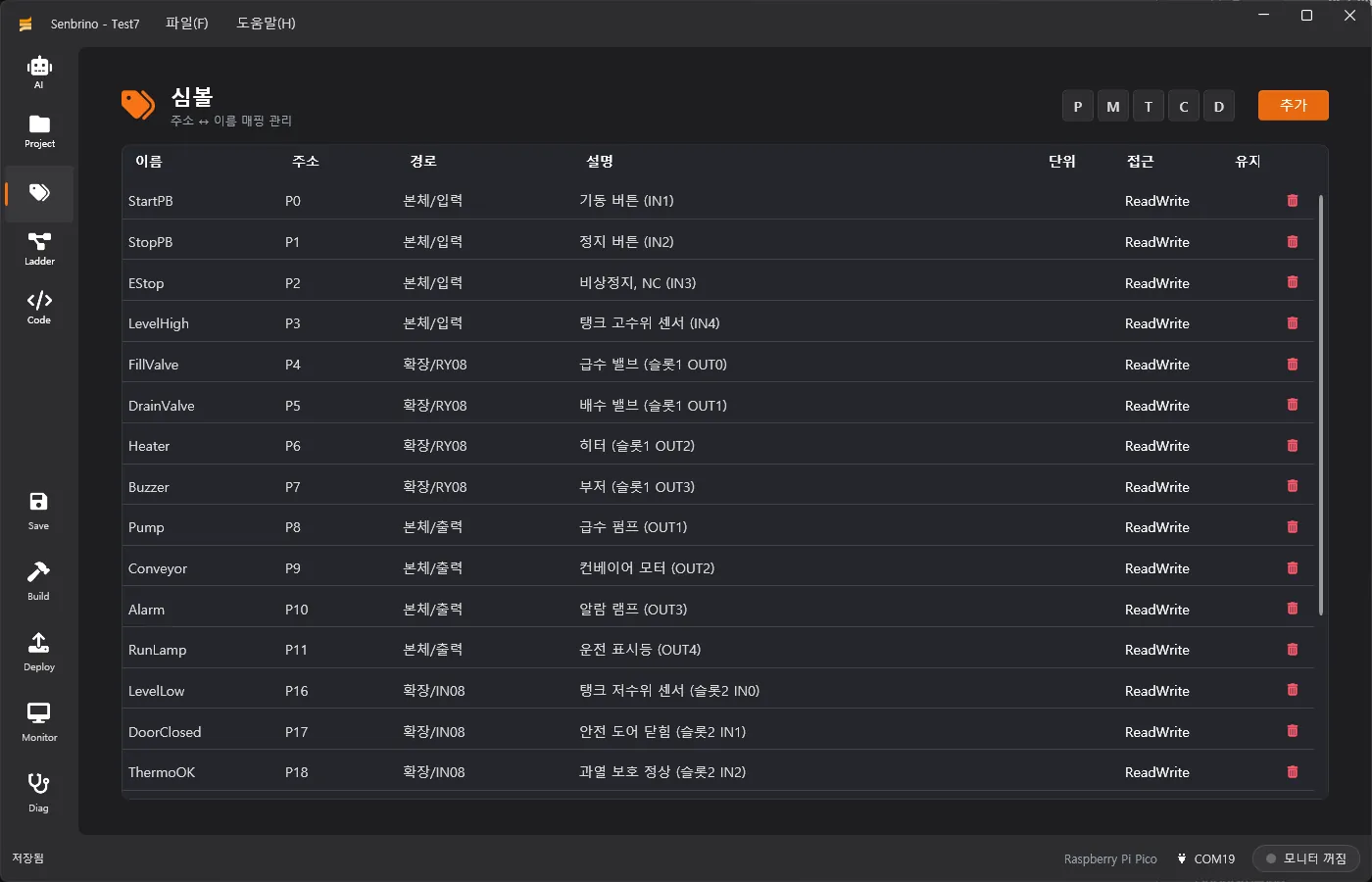
There is no need to memorize raw addresses like P0, M10 or D127. Each name-to-address mapping carries a path, a description, a unit and an access level, and the ladder refers to the name.
Mark a symbol as retentive and its value is stored in the persistent memory on the board and restored at boot. That is what running totals and setpoints need in order to survive a power cut.
Pick a board, plug in the I/O
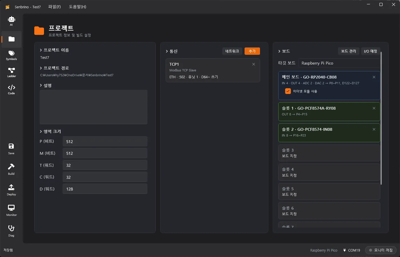
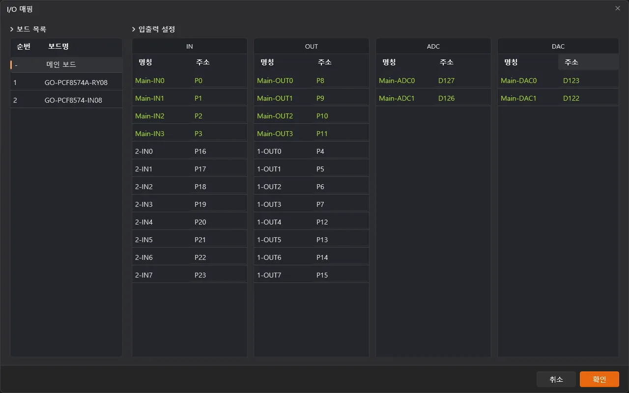
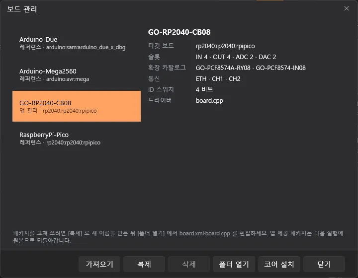
Fit cards such as the RY08 relay output or the IN08 input into the main board IN, OUT, ADC and DAC channels and into the expansion slots, and PLC addresses are assigned automatically. Slot numbers follow the rotary switch position on the card itself, so the drawing and the hardware cannot drift apart.
Board packages (board.xml plus a driver) can be imported, cloned and edited from the board manager. Adding new hardware does not mean touching application code.
What comes out is an ordinary Arduino sketch
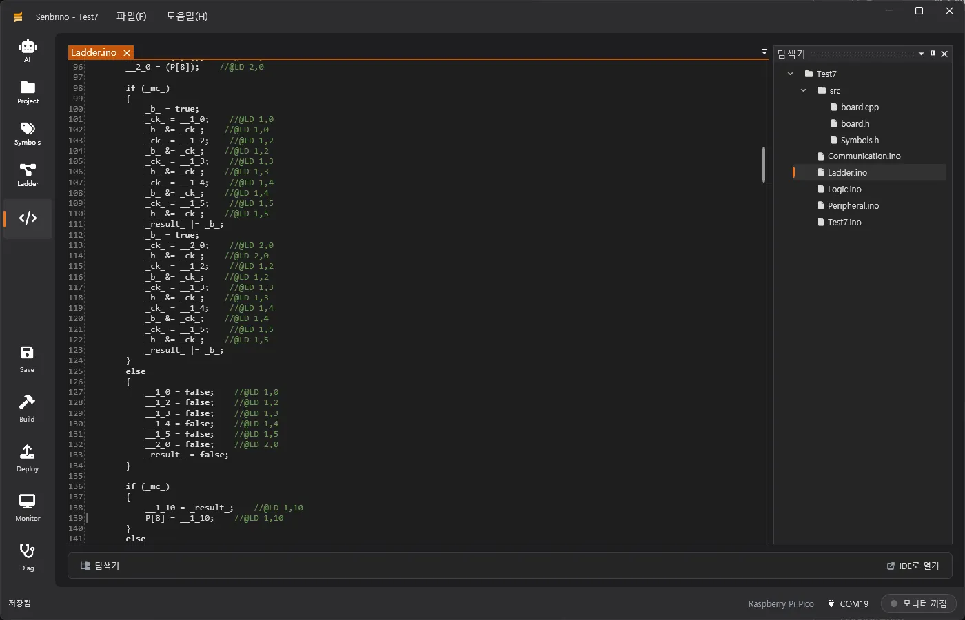
Every build regenerates Ladder.ino, Symbols.h, Peripheral.ino and Communication.ino from the ladder, symbols, pin definitions and communication setup, then compiles and uploads with the bundled arduino-cli.
The output is a readable Arduino sketch, not a black box, so hand-written code goes in Logic.ino — the one file a build never overwrites. The generated code carries //@LD row,col comments, so a compile error is traced back through those coordinates to the ladder cell it came from.
Monitor and diagnose over the upload cable
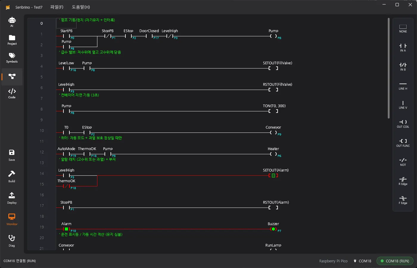
No second cable, no adapter. Over the same USB connection used for uploading, contact, coil, timer and word values appear live on the ladder itself.
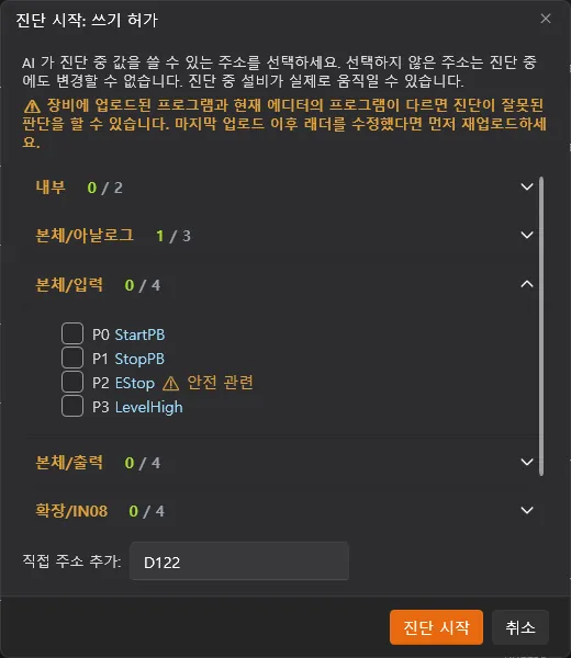
Diagnostic mode can force or write values, but only at addresses armed in advance. Anything not armed is refused by the device itself — fail-closed.
Modbus RTU and TCP
Modbus devices attach to the serial and Ethernet ports the board declares. As a slave, PLC memory is exposed directly. As a master, monitor blocks (polling) and bind tables (remote-to-local mapping) read and write the other device.
The W5500 Ethernet path includes a watchdog and a stack restart, so a communication fault recovers on its own instead of waiting for someone to drive out to the site.

AI reads and writes the ladder
Senbrino ships with a built-in MCP server. AI coding tools such as Claude Code and Codex can read and modify the ladder, symbols, communication setup and board configuration through tool calls.
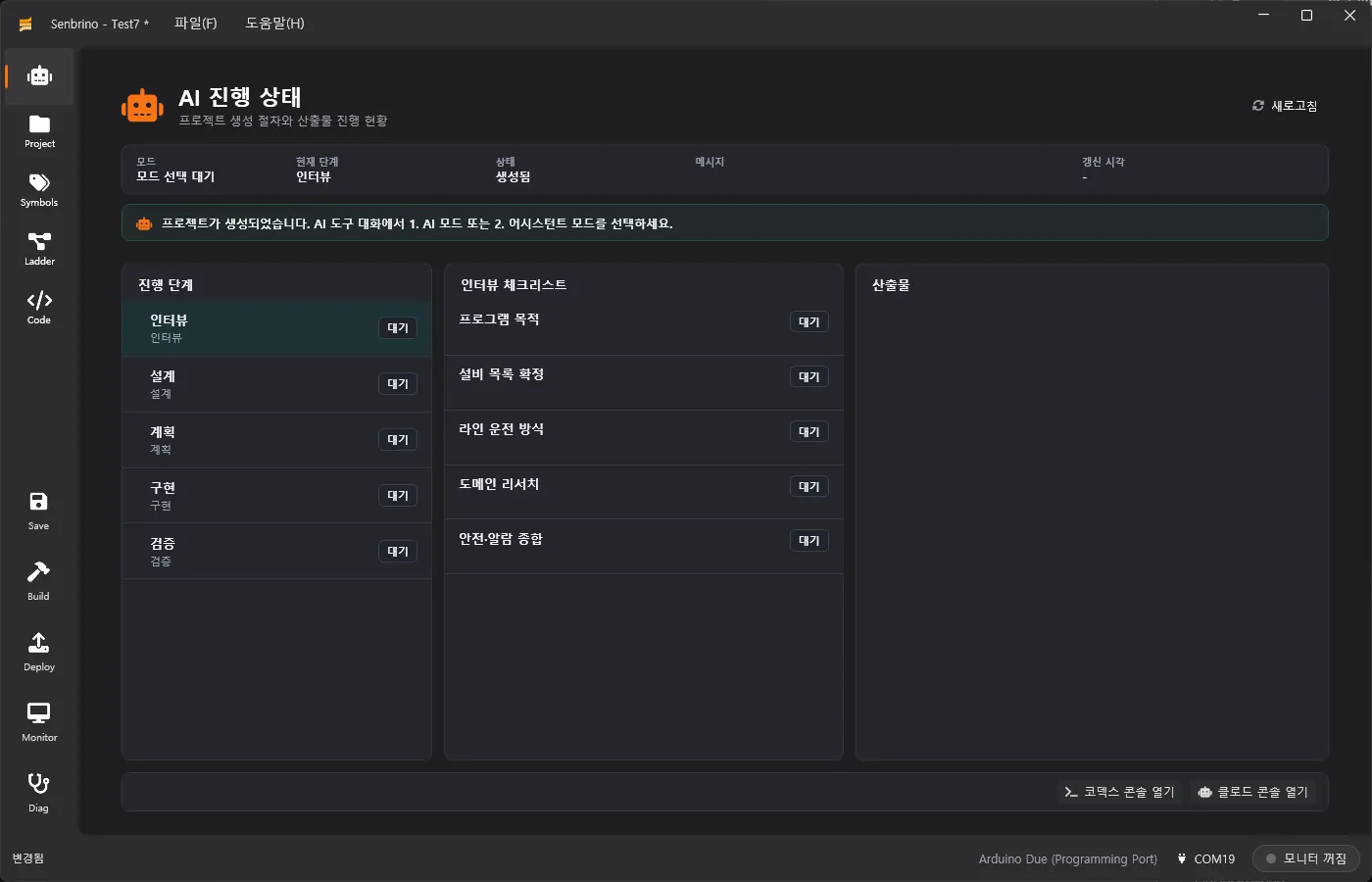
The AI page tracks the stages and artifacts of the flow — interview, design, plan, implementation, verification. In diagnostic mode the AI is held to the same armed addresses a person is, and can only read and experiment inside them.
Supported boards
| Board | Notes |
|---|---|
| GO-RP2040-CB08 (Going) | Our main board. IN 4 · OUT 4 · ADC 2 · DAC 2, Ethernet (W5500), CH1 and CH2 serial, ID rotary switch, EEPROM retentive memory, GO-LINK expansion modules |
| GO-Pico-IO8R (Going) | Our compact board. IN 4 (photocoupler isolated, DC 9–24 V) · OUT 4 (relay contacts, AC 250 V / DC 30 V 5 A) · ADC 2 (12-bit), CH1 RS232C, CH2 RS485. Modbus RTU only |
| Arduino Due | Standard Ethernet shield, 12-bit ADC and DAC |
| Arduino Mega2560 | Standard Ethernet shield, built-in EEPROM retentive memory |
| Raspberry Pi Pico | W5500 module |
| Others | Add a board package (board.xml plus a board.cpp driver) |
Installing
Download and run Senbrino-win-Setup.exe. It installs under the user account (%LocalAppData%\Senbrino), so no administrator rights are required.
If the .NET 9 desktop runtime is missing, the installer fetches it, and arduino-cli is set up on first launch. After that the app checks for new versions at startup — Help › Check for Updates downloads and restarts.
Draw the ladder, open the generated Arduino sketch and read it, monitor over the cable used for uploading. Senbrino exists so that neither the familiarity of a dedicated PLC nor the flexibility of Arduino has to be given up.
If you would like to know more about Senbrino, or you are considering it for a site, we are happy to hear from you.
Contact
- Email: [email protected]
- Instagram: https://www.instagram.com/going.sen/
- Website: https://intosen.com/kr/consult/
Comments
Enter a nickname to leave a comment, or sign in with Google or GitHub.