

Senbrino works like this: you build ladder logic in an editor on a Windows PC, and the editor turns it into Arduino code and uploads it to a board. Part 1 is the PC side. Install the editor and get to the first start screen.
How it fits together
flowchart LR
    E["Editor<br/>Windows PC"] -- "generates code" --> C["arduino-cli<br/>compile · upload"]
    C -- "USB" --> B["Board<br/>GO-RP2040-CB08"]
B -. "monitoring / diagnostics over the same USB" .-> E| Component | Runs on | Role |
|---|---|---|
| Editor | Windows PC | Edit ladder and symbols, generate code, build, deploy, monitor, diagnose |
| arduino-cli | Windows PC | Compiles the generated sketch and uploads it to the board. The editor runs it internally, so you never touch it |
| Board | Arduino-compatible board | Runs the uploaded program. There is no runtime to install |
What you need
| Item | Requirement |
|---|---|
| Editor PC | Windows 10/11 x64 |
| Board | GO-RP2040-CB08 and a USB cable. Needed in Part 2 |
| Claude Code | Used in Part 3 to write the ladder. Needs a paid plan, Pro or above |
Claude Code installs with one line in PowerShell. Run claude once afterwards and log in.
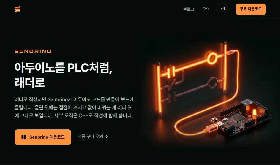
irm https://claude.ai/install.ps1 | iex1. Download the installer
2. Install
The install takes a few seconds and the editor opens right away.
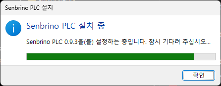
- It installs to
%LocalAppData%\Senbrino. No administrator rights needed. - If the .NET 9 desktop runtime is missing, the installer adds it. That brings up one administrator prompt.
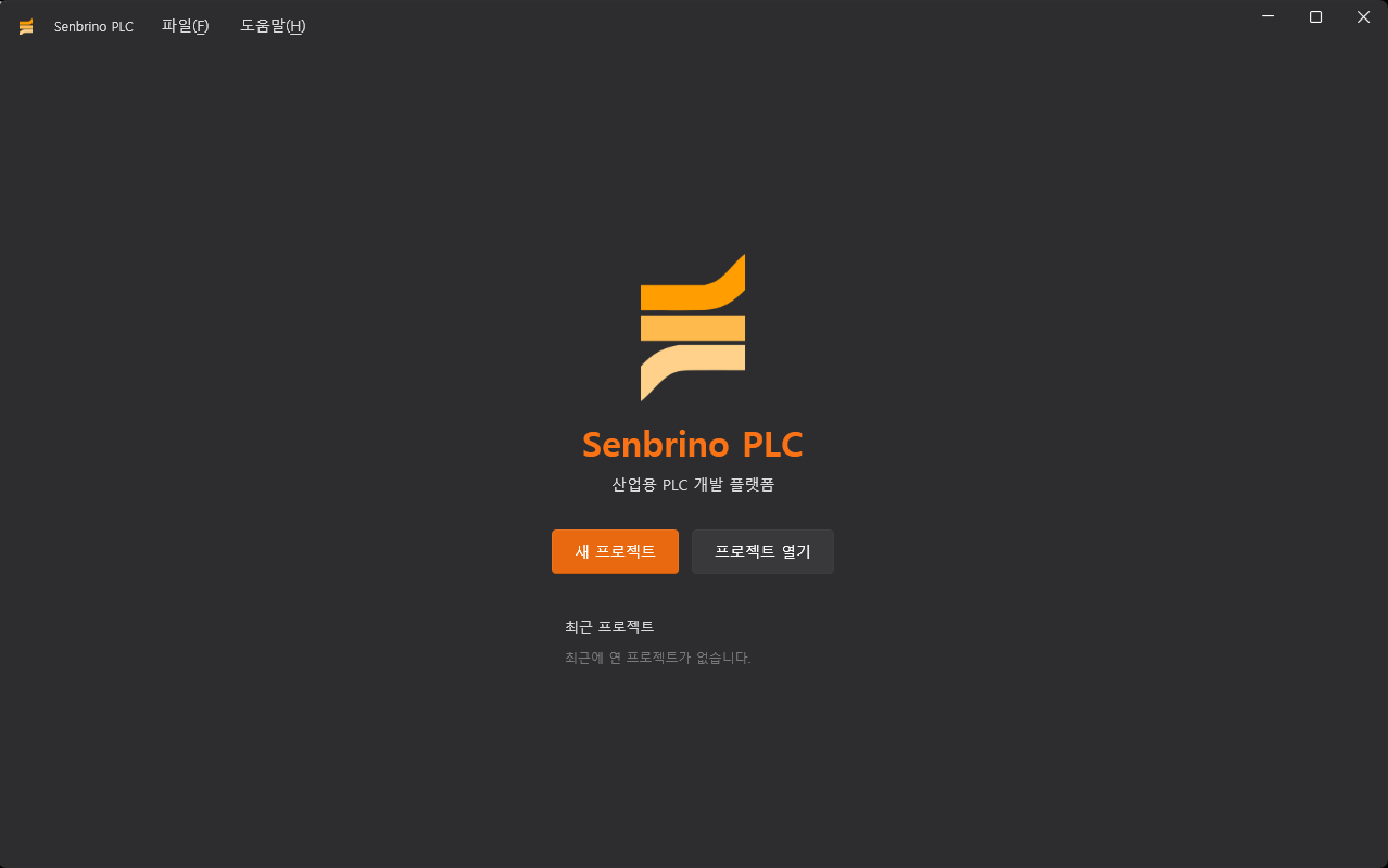
3. First start
4. Understanding boards
- Main board — the board the program runs on
- It has its own IN, OUT, ADC and DAC. One per project. Example: GO-RP2040-CB08
- Expansion card — a GO-LINK module attached next to the main board
- You can attach several. Examples: RY08 (8 relay outputs), IN08 (8 inputs)
- Board package — the definition that tells the editor about one kind of main board
- One folder per board type, with two files inside
What is in a board package
board.xml— the definition- Lists what the board has on it
board.cpp— the C++ driver- The code that actually drives that hardware. Pin layout and peripheral chips differ from board to board, so this part is split out into the package
The board used here
- The GO-RP2040-CB08 package ships with the editor
- 4 inputs, 4 outputs, 2 ADC, 2 DAC. The driver is included, so there is nothing to write
Next part
Part 2 connects the GO-RP2040-CB08 to the PC, creates a new project, and assigns it as the main board.
Comments
Enter a nickname to leave a comment, or sign in with Google or GitHub.