

Part 2 is the board side. Connect the GO-RP2040-CB08, then assign the main board and port in a new project.
What you need
| Item | Detail |
|---|---|
| Board | GO-RP2040-CB08 |
| Cable | USB Type-B |
| Power | DC 24 V |
| Buttons | 2 push buttons (start, stop) |
| PC | The Windows PC with the editor from Part 1 |
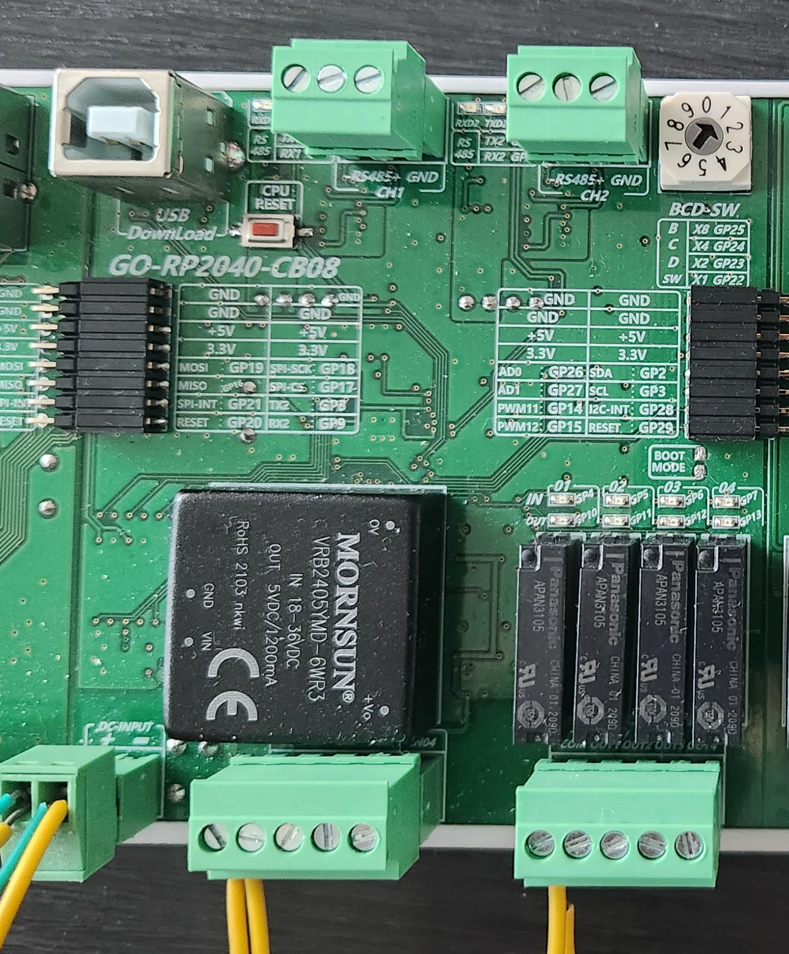
GO-RP2040-CB08
| Item | Spec |
|---|---|
| Power input | DC-INPUT + −, DC 24 V (18 to 36 V) |
| Digital inputs | 4 (IN01 to IN04, common COM). Photocoupler isolated, non-polar, DC 24 V |
| Relay outputs | 4 (OUT1 to OUT4, common COM). NO contact, 5 A 250 VAC / 5 A 30 VDC |
| Analog | 2 ADC, 2 DAC |
| Comms | RS-485, 2 channels (CH1, CH2) |
| PC connection | USB Type-B (USB DownLoad) |
| Indicators | 4 input LEDs, 4 output LEDs |
Terminals and addresses
| Terminal | GPIO | Address | Terminal | GPIO | Address | |
|---|---|---|---|---|---|---|
| IN01 | GP4 | P0 | OUT1 | GP10 | P4 | |
| IN02 | GP5 | P1 | OUT2 | GP11 | P5 | |
| IN03 | GP6 | P2 | OUT3 | GP12 | P6 | |
| IN04 | GP7 | P3 | OUT4 | GP13 | P7 |
These are the addresses with the main board alone. Adding expansion cards pushes the output addresses back. The ladder in Part 3 uses these addresses.
1. Wire the buttons
| Terminal | Connect to |
|---|---|
DC-INPUT + / − | DC 24 V supply |
IN01 | 24 V + through the start button |
IN02 | 24 V + through the stop button |
Input COM | 24 V − |
2. New project and main board
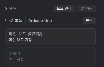
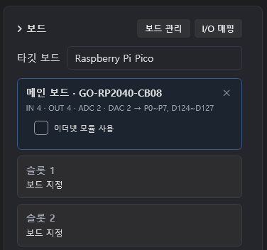
Once assigned, the Board box changes to this.
| Item | State |
|---|---|
| Target Board | Top of the Board box. Switches to Raspberry Pi Pico on its own |
| Addresses | Inputs P0 to P3, outputs P4 to P7. Change them under I/O Mapping |
| Use Ethernet module | Leave it off. Turn it on only when an Ethernet board (GO-LINK W5500) is attached |
| Slots 1 to 9 | Places for expansion cards. Left empty in this series |
The Test project is used through Part 3.
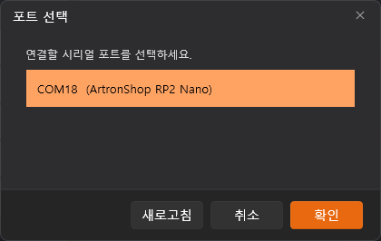
3. Select the port
Next part
Part 3 writes the ladder with AI and deploys it to the board to move a relay.
Comments
Enter a nickname to leave a comment, or sign in with Google or GitHub.