
PICO-IO8R is an RP2040 I/O board with four digital inputs, four relay outputs, and RS-232C and RS-485 ports. Its power input range is DC 12 to 24 V.
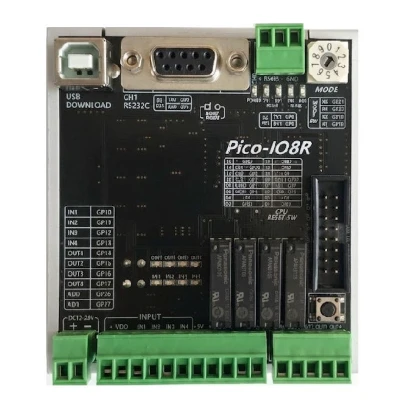
Ratings and operating conditions
| Item | Specification |
|---|---|
| Model | PICO-IO8R |
| CPU | RP2040 |
| Nominal power input | DC 24 V |
| Power input range | DC 12 to 24 V |
| Digital inputs | 4 points |
| Digital outputs | 4 relay contacts |
| Input signal voltage and current | DC 9 to 24 V, 10 mA maximum |
| AC output load rating | 0 to 250 VAC, 5 A |
| DC output load rating | 0 to 30 VDC, 5 A |
| Operating temperature | -10 to 50°C |
| Ambient humidity | 10 to 95% RH, noncondensing |
| Dimensions | 77 × 85.2 × 34.8 mm |
The board supply and digital inputs have different voltage ranges: DC 12 to 24 V at the power terminals and DC 9 to 24 V at the digital inputs. The relay load rating depends on whether the load uses AC or DC.
Digital inputs and relay outputs
The input terminals are IN1 to IN4. The input circuit uses photocoupler isolation, and the circuit sheet describes the input common as bidirectional and nonpolar. Green LEDs indicate input activity.
The output terminals are OUT1 to OUT4 and COM. The output circuit sheet specifies relay contacts, photocoupler isolation, a 10 ms response time and red status LEDs.
| Channel | Input terminal | Input GPIO | Output terminal | Output GPIO |
|---|---|---|---|---|
| 1 | IN1 | GPIO_10 | OUT1 | GPIO_14 |
| 2 | IN2 | GPIO_11 | OUT2 | GPIO_15 |
| 3 | IN3 | GPIO_12 | OUT3 | GPIO_16 |
| 4 | IN4 | GPIO_13 | OUT4 | GPIO_17 |
RS-232C and RS-485
RS-232C uses the CH1 D-sub connector. RS-485 uses the upper terminal block, labeled D+, D− and GND in the board layout.
| Interface | Signal | GPIO |
|---|---|---|
| RS-232C | TX0 | GPIO_0 |
| RS-232C | RX0 | GPIO_1 |
| RS-485 | TX1 | GPIO_8 |
| RS-485 | RX1 | GPIO_9 |
This table maps the board GPIOs to communication signals. It is separate from the physical pin numbering of the D-sub connector.
Additional pins in the board layout
The layout also labels AD0 and AD1 and the GPIOs for the MODE switch.
| Function | Board label | GPIO |
|---|---|---|
| Analog | AD0 | GP26 |
| Analog | AD1 | GP27 |
| MODE switch | X1 | GP18 |
| MODE switch | X2 | GP19 |
| MODE switch | X4 | GP20 |
| MODE switch | X8 | GP21 |
The supplied specifications do not state the input voltage range for AD0 or AD1. The digital inputs’ DC 9 to 24 V rating does not apply to these analog terminals.
The product photo also shows the USB DOWNLOAD port, BOOT MODE button and CPU RESET-SW.
Related software
PICO-IO8R appears in the Senbrino supported board list, which describes the development environment and its use.
Sources
This article uses the supplied PICO-IO8R ratings, GPIO tables, board layout and I/O circuit descriptions. The output load ratings follow the main ratings table, which specifies separate limits for AC and DC.
Comments
Enter a nickname to leave a comment, or sign in with Google or GitHub.