
PCB design automation started with one goal: put in the design intent, get out the Gerbers. These ten posts cover replacing more than twenty years of hand-drawn PADS schematics and layout with generated KiCad files.
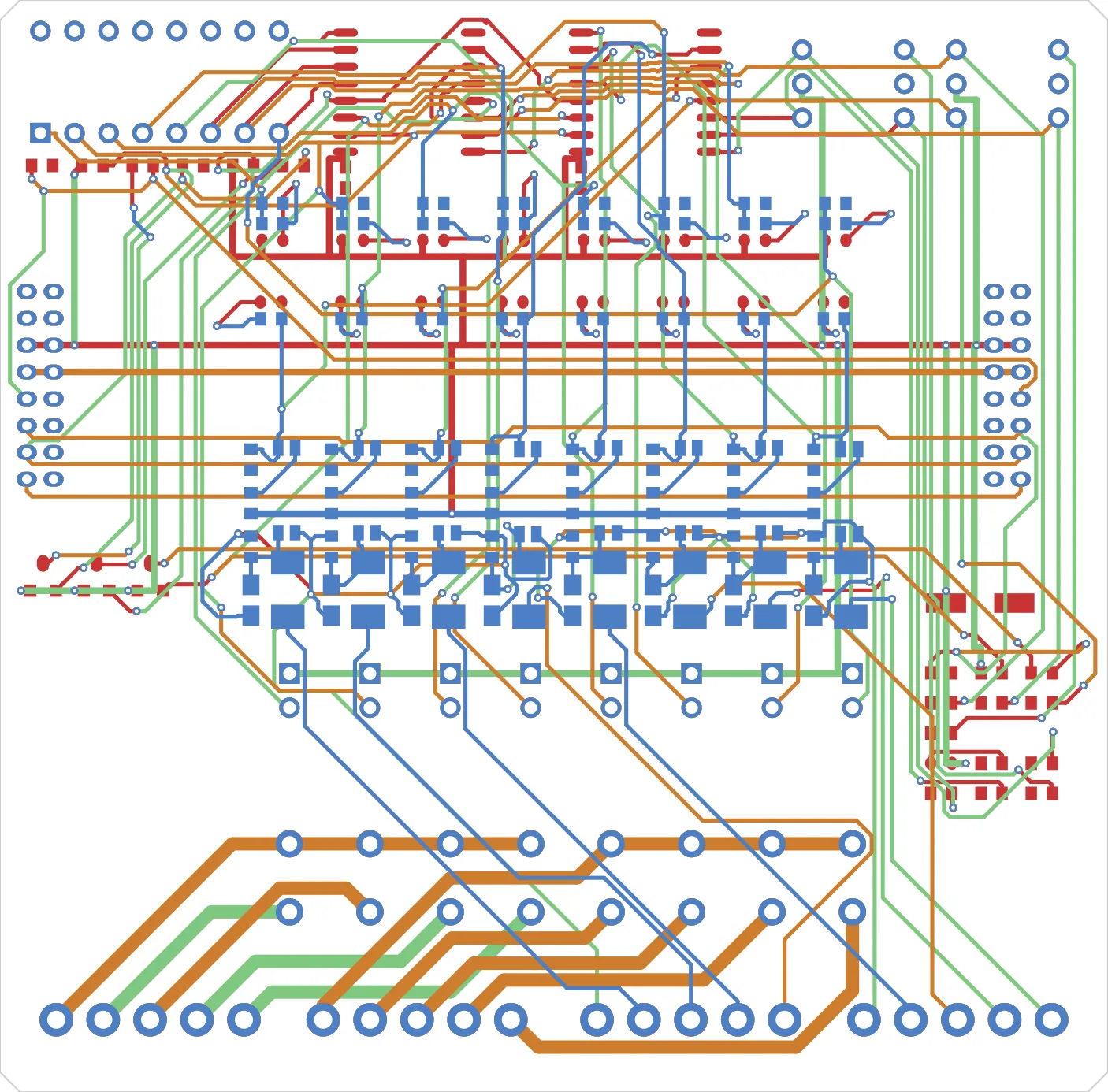
This is not a success story. A board came out 1.5× too large after passing every gate, the measuring tool was modifying the thing it measured, and we declared something “physically impossible” three times and were wrong all three times. Here is the whole run, in order.
Building the pipeline
Schematic generation from design intent comes first. Everything downstream is discarded if this is wrong, so the gates here are dense.
- PCB design automation verification - the 1.5× board that passed every gate A misread PADS ASCII unit scaled parts, traces, and the outline by the same factor. Every internal consistency check stayed green while the board was wrong.
- PCB design automation library - one backslash and a 3D model rabbit hole Moving 1,214 footprints and 857 symbols across. A single backslash broke an entire library file.
When the routing will not close
The autorouter and DRC, in three parts. Every rule DRC does not check needed a checker of its own.
- PCB design automation autorouting - 45°, staircases, and three failures The 45° rule, staircase traces, and antenna stubs. Per-layer routing direction had to be injected into the DSN file directly.
- PCB design automation DRC - the measurement was changing the board The check command was overwriting the board. If the measurement changes its subject, it is not data.
- PCB design automation four layers - good numbers, bad routing The numbers confirmed we were squeezing a 16-channel board into two layers, so we moved to four.
The last one
The slowest stretch in automation was never the first 90 percent. It was the last few nets.
- PCB design automation last mile - unrouted nets, shorts, and DRC noise Shorts over unrouted nets over clearance, in that order. Blocked spots were solved by moving the wall in a single transaction.
- PCB design automation done - DRC 0, zero arbitrary angles, and 0.1mm DRC 0, unrouted 0, shorts 0 - measured five times, same value five times.
After calling it finished
Three posts written after we wrote “done.” What we believed we had verified fell apart under review, and the two after that put the same method on new boards.
- PCB design automation review - the things we thought we had verified A metric passing is not evidence that the metrics you never took would pass.
- PCB design automation placement loop - before you say it cannot be done Three declarations of “physically impossible,” three mistakes. Placement selection went into the loop.
- PCB design automation isolation barrier - our ruler disagreed with KiCad ten times Twenty years of low-voltage control boards, then a first 220V motor brake rectifier. Our grid and KiCad DRC disagreed ten times, and every time ours was the more permissive one.
What the series comes down to
PCB design automation kept returning to one point. Gates only check that the things we generated agree with each other. If the input reading is wrong, every gate stays green and the output is still wrong.
- Cross-check units and scale against something outside the files: manufacturing CAM, real part pitch
- Confirm the measuring command does not write to what it measures
- Anything DRC ignores - angles, silkscreen, assembly clearance - needs its own checker
- “Physically impossible” is a conclusion only after it has been proven in coordinates
The quality of an automated pipeline comes from the density of its gates, not the cleverness of its generator.
Contact
- Email: [email protected]
- Instagram: https://www.instagram.com/going.sen/
- Website: https://intosen.com/kr/consult/
Comments
Enter a nickname to leave a comment, or sign in with Google or GitHub.