

Part 2 is the Raspberry Pi side. Flash the OS, install the runtime, then register the Pi-SD16R board in the editor.
What you need
| Item | Detail |
|---|---|
| Boards | Raspberry Pi 5, Pi-SD16R carrier board |
| Storage | microSD card (16 GB or more) and a card reader |
| Power | DC 12 to 24 V adapter |
| PC | The Windows PC from Part 1 with the editor installed, on the same network as the Pi |
| Software | Raspberry Pi Imager, PuTTY |
The Pi-SD16R board
A carrier board that sits on the Pi’s 40-pin header. It powers the Pi and gives you 4 isolated inputs, 4 relay outputs and one RS-485 channel.
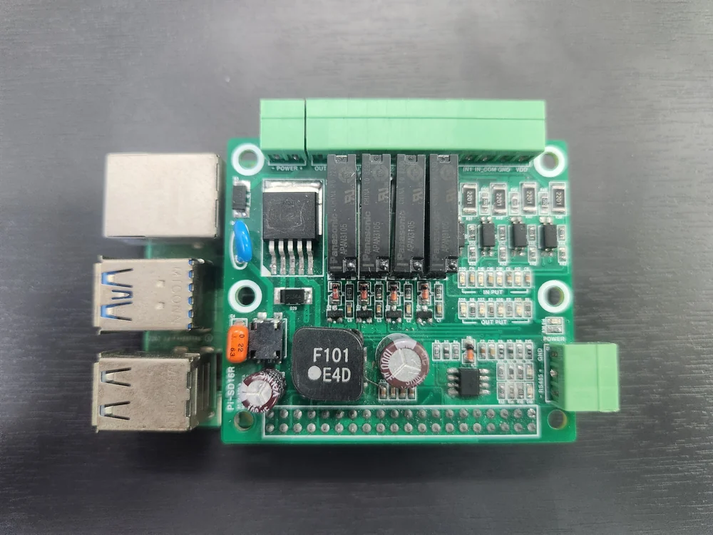
| Item | Spec |
|---|---|
| Power input | POWER +/-, DC 12 to 24 V. An onboard 5 V regulator feeds the Pi |
| Digital inputs | 4 (IN1 to IN4, common IN_COM). Photocoupler isolated (2,500 Vrms), non-polar, DC 12 to 24 V |
| Relay outputs | 4 (OUT1 to OUT4, common OUT_COM). Form A, 5 A 250 VAC / 5 A 30 VDC |
| RS-485 | 1 channel, half duplex, automatic direction control, up to 500 kbps. Terminals 485+, 485-, GND |
| Indicators | POWER, 4 inputs, 4 outputs, RS-485 TX/RX LEDs |
| Other | VDD terminal outputs the input supply (for sensor power). POWER_SW switches power to the Pi on and off |
GPIO pin map
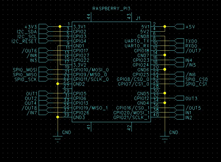
| Slot | GPIO (BCM) | Header pin | Slot | GPIO (BCM) | Header pin | |
|---|---|---|---|---|---|---|
| IN1 | GPIO20 | 38 | OUT1 | GPIO5 | 29 | |
| IN2 | GPIO21 | 40 | OUT2 | GPIO6 | 31 | |
| IN3 | GPIO22 | 15 | OUT3 | GPIO12 | 32 | |
| IN4 | GPIO23 | 16 | OUT4 | GPIO13 | 33 |
RS-485 uses UART0 (GPIO14/15). Inputs and outputs are both active high, so the XML needs no invert.
1. Flash Raspberry Pi OS
In Raspberry Pi Imager pick device Raspberry Pi 5, OS Raspberry Pi OS Lite (64-bit), storage the microSD card.
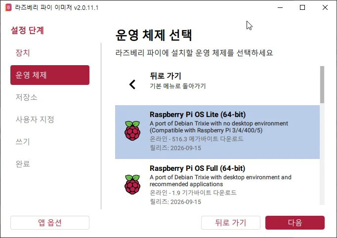
Fill in the customisation settings:
| Item | Value |
|---|---|
| Hostname | senbrix |
| User | pi / raspberry. Use a different password on real equipment |
| Wi-Fi | SSID and password. Skip it on wired |
| Remote access | Turn on SSH, password authentication |
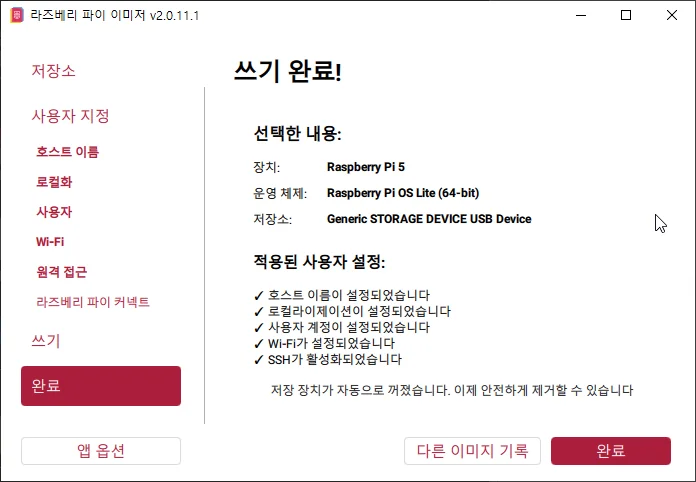
When the write finishes, the completion screen lists the settings that were applied.
2. Boot and connect over SSH
Insert the microSD, seat the Pi-SD16R on the 40-pin header, and feed power into the POWER terminals. First boot takes two to three minutes.
Connect to senbrix.local with PuTTY. If it does not resolve, look up the IP on your router.
ping senbrix.localLog in as pi with the password you set in Imager.
3. Install the runtime
curl -sSL https://raw.githubusercontent.com/going-kr/Release.Senbrix/master/install-runtime.sh | sudo bash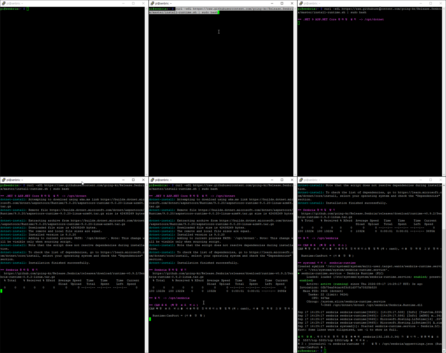
At the CAN expansion board question, just press Enter. When you see Active: active (running) at the end, you are done. It starts on every boot from now on.
systemctl status senbrix-runtime
journalctl -u senbrix-runtime -f- Update: run the same command again
- Firewall: open
5557/tcp,5555/tcp,5353/udp
4. New project and device check
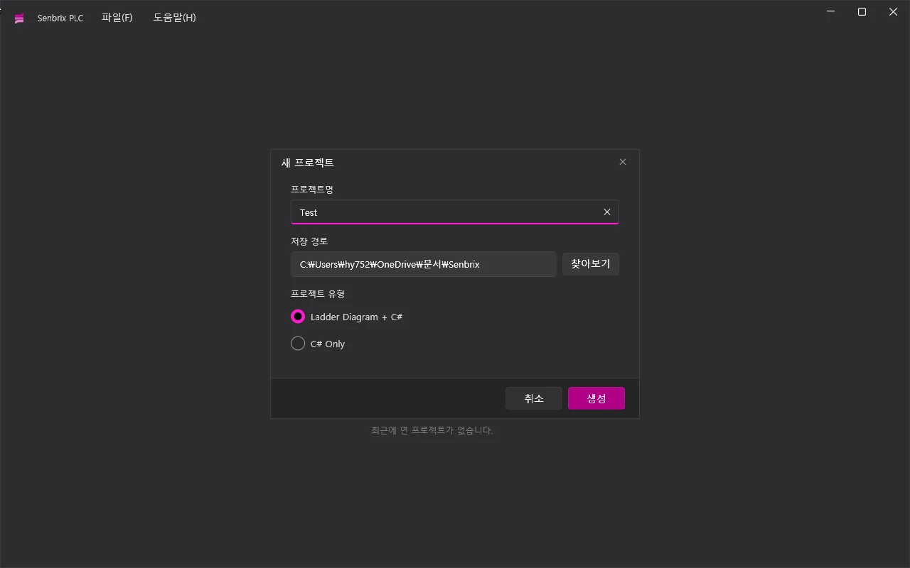
On the editor start screen click New Project. Name it Test, keep the default location, and pick Ladder Diagram + C# as the project type. Click Create and the project screen opens. You will use this project through Part 3.
Click the connection icon at the bottom of the editor and the Connect Device dialog lists senbrix. If it does not, type the IP in directly.
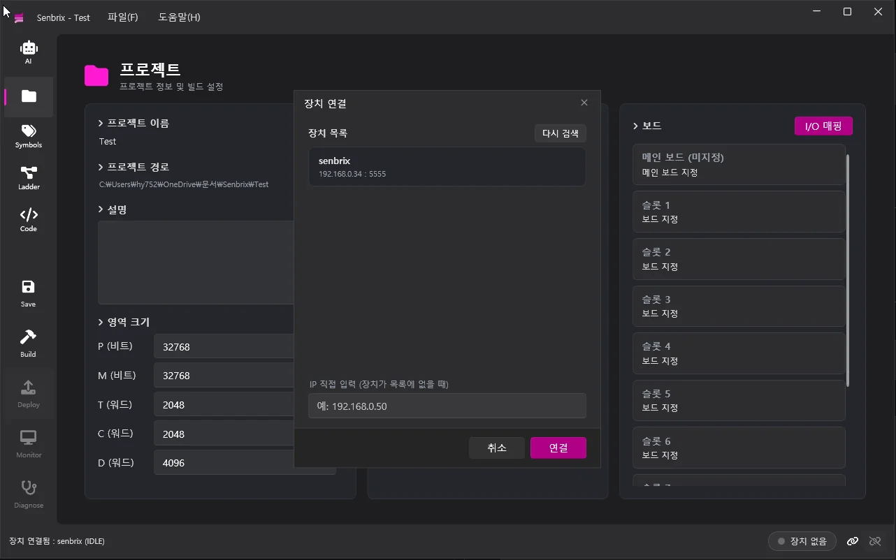
Click Connect and the status bar shows the IP and state.

5. Register the Pi-SD16R main board XML
Open the main board definitions folder.
explorer %LocalAppData%\Going\Senbrix\MainBoardsCreate Pi-SD16R.xml.
<MainBoard name="Pi-SD16R" version="1">
  <Pin gpio="20" slot="IN1"  direction="In"/>
  <Pin gpio="21" slot="IN2"  direction="In"/>
  <Pin gpio="22" slot="IN3"  direction="In"/>
  <Pin gpio="23" slot="IN4"  direction="In"/>
  <Pin gpio="5"  slot="OUT1" direction="Out"/>
  <Pin gpio="6"  slot="OUT2" direction="Out"/>
  <Pin gpio="12" slot="OUT3" direction="Out"/>
  <Pin gpio="13" slot="OUT4" direction="Out"/>
</MainBoard>| Attribute | Meaning |
|---|---|
gpio | BCM number. No duplicates |
slot | IN<n> / OUT<n> |
direction | In / Out |
pull, invert | Input pull-up/down, active-low inversion. Not needed for the Pi-SD16R |
On the project screen, click Assign Main Board in the Board panel on the right and pick Pi-SD16R from the Select Main Board dialog. You can also skip the folder and pick the XML file directly with Browse.
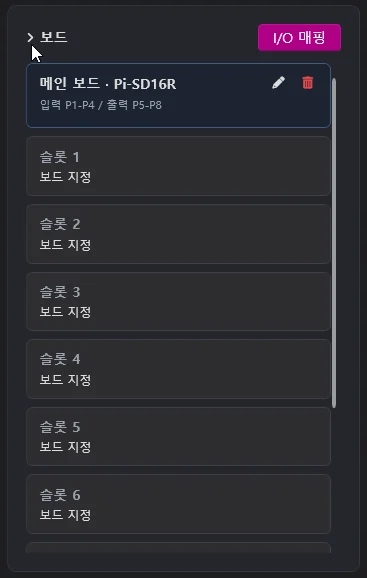
Click OK and the board panel shows Main board · Pi-SD16R, with inputs bound to P1 to P4 and outputs to P5 to P8. Change that under I/O Mapping if you need to.
Next
Part 3 has AI write a small control program, deploys it to the Pi, and moves the relays.
Comments
Enter a nickname to leave a comment, or sign in with Google or GitHub.