

Part 3 is the program. Open the project from Part 2, ask the AI for a ladder in one line, deploy it to the Pi, and move a relay.
What you need
| Item | Detail |
|---|---|
| Parts 1 and 2 done | Editor installed, runtime on the Pi, Pi-SD16R assigned as main board in the Test project |
| Claude Code | Installed and logged in as in Part 1. Without it the console button stays disabled |
| Input wiring | Push buttons on IN1 and IN2 |
| Starting point | The Test project from Part 2 open and connected to the Pi through the connection icon (Part 2, section 4) |
1. Open the Claude console
Click AI in the left menu. It still says “Awaiting mode selection”. Click Open Claude Console at the bottom right and a Claude Code terminal opens beside the editor, reads the project state, and asks its first question.
How should we start this project? 1. AI mode / 2. Assistant mode
Answer 2.
| Mode | What it does |
|---|---|
| AI mode | The AI drives interview, design, plan, implementation and verification step by step, asking for approval at each gate |
| Assistant mode | For building right now, like this. No gates. Ask and it edits |
When the AI page shows mode “Assistant mode” and current phase “Assistant ready”, you are set.
2. Ask for the ladder in one line
Type this into the console.
On main board Pi-SD16R, make a latching circuit: pressing IN1 turns OUT1 on, pressing IN2 turns it off.
Three seconds after OUT1 comes on, turn OUT2 on as well. Use the board bindings for addresses (inputs P1-P4, outputs P5-P8).
The AI checks the board bindings, adds symbols, writes the ladder, verifies it with lint and a build, then reports back. It takes about a minute.
The generated symbols
Check them under Symbols in the left menu.
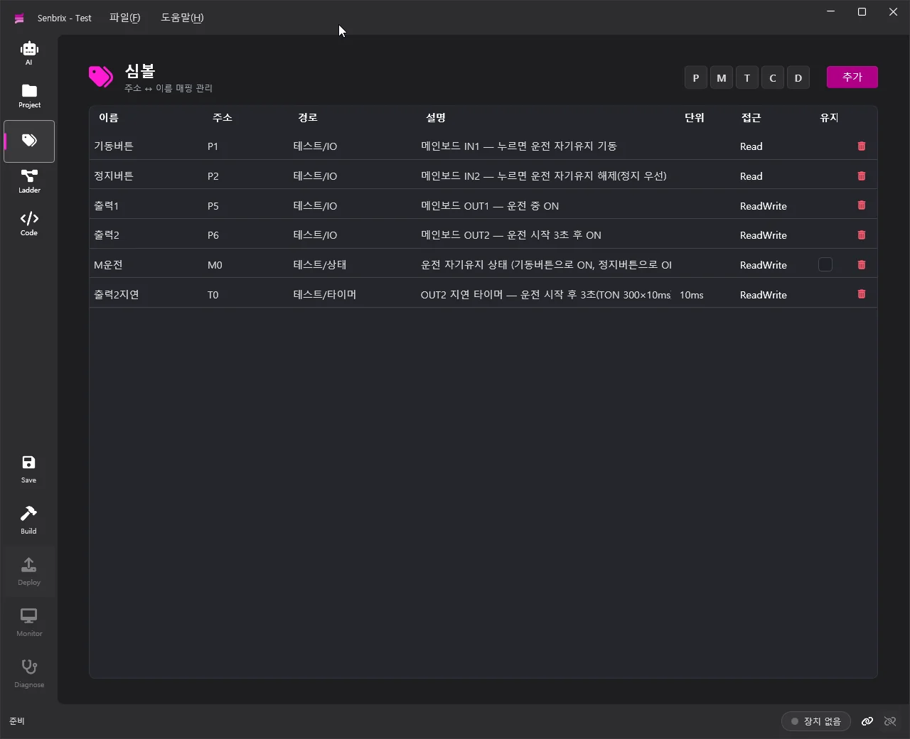
| Name | Address | Role |
|---|---|---|
| Start button | P1 | Main board IN1 |
| Stop button | P2 | Main board IN2 |
| Output 1 | P5 | Main board OUT1 |
| Output 2 | P6 | Main board OUT2 |
| Running | M0 | Latched run state |
| Output 2 delay | T0 | TON timer, 10 ms units |
The generated ladder
Check it under Ladder. Four rungs.
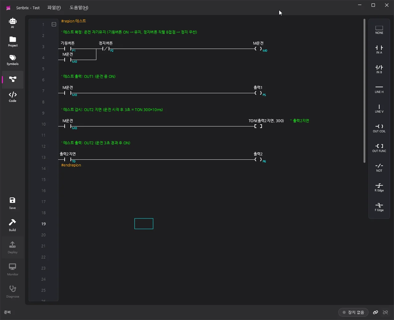
| Rung | Content |
|---|---|
| 1 | Start button ∥ Running → Stop button NC contact → Running coil. Stop-priority latch |
| 2 | Running → Output 1 |
| 3 | Running → TON(Output 2 delay, 300). 10 ms × 300 = 3 s |
| 4 | Output 2 delay → Output 2 |
3. Deploy
Click Deploy in the left menu. Save, build and deploy run back to back. The status bar reads Deploy complete: runtime running and the device indicator switches to (RUN).
To build on its own, click Build. If there are errors, a list comes up and points you at the ladder cell.
4. Check it in the monitor
Click Monitor. Contact states and the timer’s current value show live on the ladder.

| Action | What you see |
|---|---|
Press IN1 | Running ON, Output 1 ON. The OUT1 relay on the board closes and its LED lights |
| 3 seconds pass | Output 2 delay reaches 300, Output 2 goes ON. The OUT2 relay closes |
Press IN2 | Running OFF. Output 1, the timer and Output 2 all drop together |
The monitor is read-only. Forcing values is what Diagnose (diagnostics mode) is for, and this series does not cover it.
Recap
| Part | What you did |
|---|---|
| Part 1 | Editor and .NET 9 SDK on Windows |
| Part 2 | Runtime on the Pi, Pi-SD16R main board XML |
| Part 3 | Ladder from AI, deploy, monitor |
Comments
Enter a nickname to leave a comment, or sign in with Google or GitHub.